
motor driver circuit

H-bridge circuits are pivotal in controlling the direction and speed of DC motors in various applications, particularly in robotics. The H-bridge configuration consists of four switches (transistors or MOSFETs) arranged in a bridge formation, which allows the voltage to be applied across the motor in either direction. By selectively turning on and off these switches, the current flow through the motor can be reversed, enabling it to rotate in both clockwise and counterclockwise directions.
When implementing an H-bridge, it is essential to consider the control logic that dictates which switches are activated. Typically, two switches on one side of the bridge are turned on to allow current to flow in one direction, while the opposite pair is turned off. To reverse the motor's direction, the switches are toggled accordingly. Additionally, to achieve an electric braking effect, both switches on one side can be activated simultaneously, creating a short circuit across the motor terminals and rapidly dissipating the motor's kinetic energy.
H-bridges can be implemented using discrete components such as bipolar junction transistors (BJTs) or MOSFETs, allowing for custom designs tailored to specific requirements, such as current handling and switching speed. Alternatively, integrated circuits designed for H-bridge applications simplify the design process, providing built-in protection features and control logic, thus enhancing reliability and performance.
In summary, H-bridge circuits serve as a fundamental component in robotic systems, facilitating the precise control of DC motors through reversible operation and effective braking mechanisms. Their versatility in both integrated and discrete forms makes them suitable for a wide range of applications in modern electronics.These circuits are often used in robotics to allow DC motors to run forwards, backwards and to give electric break(short circuit condition). H bridges are available as integrated circuits, or can be built from discrete components as figure 1.
🔗 External reference
Related Circuits
A series of emails have been received requesting schematics for infrared remotes. This document presents a schematic for such a remote, which transmits a tone using an infrared LED. The tone is decoded by the receiver, ensuring that the...
This circuit features an adjustable output timer capable of re-triggering at specified intervals. The output duration can range from a fraction of a second to over half an hour, with the ability to recur at regular intervals spanning from...
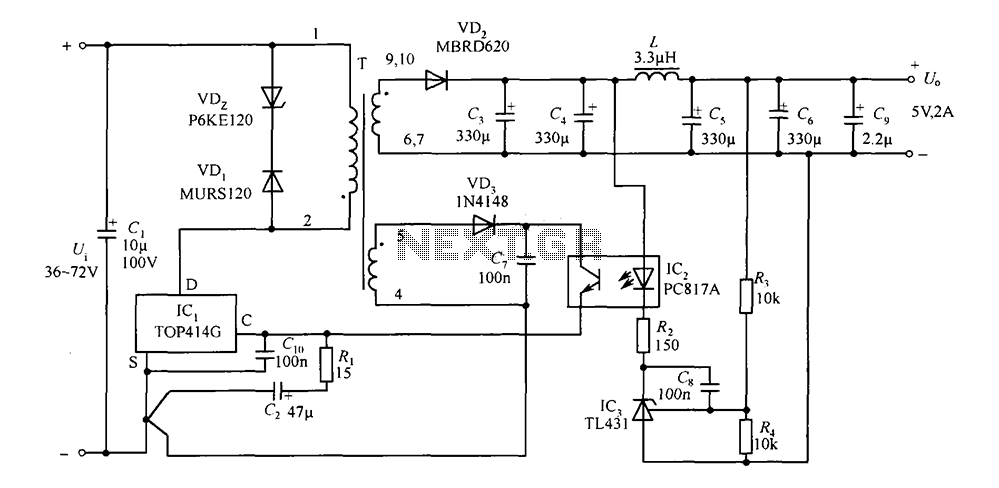
The circuit consists of a 5V TOP414G isolated switching power supply with a 2A output. C1 serves as the input filter capacitor. The circuit includes a voltage clamp protection mechanism composed of VD1. The control terminal is connected to...
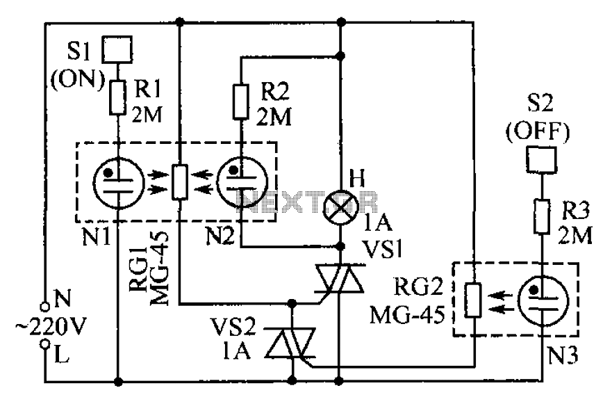
The circuit operates based on the principle that neon tubes N1, N2, and the photosensitive resistor RG1 form an optocoupler. When a finger touches the metal sheet S1, N1 lights up, causing RG1's resistance to decrease. This reduction allows...

The CMOS amplifier is biased into the linear region by resistor RB. The pi-type crystal network (C1 and C2, and XTAL) provides the 180-degree phase shift at the resonant frequency, which causes the circuit to oscillate. The described circuit utilizes...
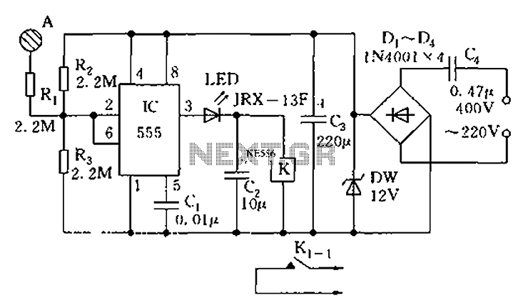
The touch sensor switch circuit diagram features a step-down rectifier circuit, a 555 timer, and flip-flops. When a hand touches the metal sheet A, the sensor signal activates the internal comparator of the 555 timer, setting the output to...