
High-accuracy ultrasonic range measurement system because of ߀?s C OS and ARM processor

The mobile robot employs a sophisticated ultrasonic range-finding system that enhances its navigational capabilities in diverse environments. The ultrasonic sensors, which are integral to the robot's functionality, operate by emitting high-frequency sound waves and measuring the time taken for the echoes to return after striking an obstacle. This round-trip time measurement is critical for accurately determining the distance to nearby objects, allowing the robot to navigate safely and efficiently.
The piezoelectric ultrasonic generator is a key component of the sensor system. It utilizes piezoelectric crystals that, when electrically stimulated, resonate at a specific frequency, producing ultrasonic waves. This mechanism is efficient and responsive, enabling rapid data acquisition and processing. The dual functionality of the piezoelectric elements—acting as both transmitter and receiver—maximizes the sensor's utility in real-time applications.
The system architecture is modular, which enhances maintainability and scalability. Each functional module serves a distinct purpose, from data acquisition to user interface display. The back wave A/D gathering module is responsible for capturing the ultrasonic return signals and converting them into digital data for further processing. The LED display and key processing module allows for user interaction, providing feedback on system status and facilitating user inputs. The LCD display module serves as the primary interface for presenting navigational data and sensor readings, ensuring that operators can easily monitor the robot's environment.
The data processing module integrates alarm systems and communication protocols, ensuring that critical information is relayed to the operator in real-time. This modular approach, combined with the robust capabilities of the LPC2138 microcontroller, allows for efficient processing and management of the robot's functions, ensuring reliable operation in unpredictable environments.
In conclusion, the mobile robot's design leverages advanced ultrasonic sensing technology, a modular software architecture, and a powerful microcontroller to achieve autonomous navigation and obstacle avoidance in complex environments. The system's ability to process real-time data and respond dynamically to its surroundings showcases the integration of electronics engineering principles in robotics applications.The mobile robot should run under the unknown and uncertain environment, must possess autopilot and avoid hindering the function. The ultrasonic static is used as the range finding sensor of the mobile robot extensively with its characteristic simple, fast with of low price in information processing, realize that avoids functions such as hindering, positioning,
environmental modeling and navigation, etc. Supersonic wave is a propagation mode of the straight line, the frequency is high, reflecting capacity is strong. Its propagation velocity is 340 m/ s in the air, easy to control, is slilghtly influenced by environment.
So the sensor of unexpected turn of of adopting and having children outside the state plan is as what the distance is surveyed Eyes , Can be used for the ultrasonic frequency band with frequency of 20- 400 kHz of the range finding field, it is 40 kHz to be daily in the air medium. The piezoelectric type ultrasonic generator utilizes crystalline syntony work of piezoelectricity in fact.
The internal structure of the ultrasonic generator has 2 piezo-electric crystal plate and a sound board. When the extra pulse signal of two electrodes of it, its frequency means the inherent oscillating frequency of the piezo-electric crystal plate, the resonance will take place in the piezo-electric crystal plate, and will drive the sound board to shake and produce supersonic wave.
On the contrary, if two inter-electrode not applied voltage, when the sound board has received supersonic wave, will oppress the piezo-electric product slice and shake, change the mechanical energy into the electric signal, become the ultrasonic receiver at this moment. To some one party to launch supersonic wave, begin to time while launching ultrasonic transmitter, supersonic wave travel in air, meet obstacle recycle back to immediately right away.
The ultrasonic receiver receives the backward wave and stops timing immediately, the propagation velocity of supersonic wave in the air is 340 m/ s. In the system, ultrasonic range finding adopts the way of measuring ultrasonic round trip time. Because the length is proportional to distance that the sound passes, when the ultrasonic emitter sends out a transient pulse wave, time to begin; Stop immediately when the ultrasonic receiving end is received after the 1st returns to the wave pulse, count.
According to time t that the time-recorder is recorded, the computable distance from obstacle s of launching point, Namely: s =340t/ 2. This is the so-called mistiming distance measuring method. This system adopts C/ OS-lI operating system, the system divides software into 4 pieces of function module: The back wave A/D is gathered the module, LED reveals and key set puocessing module, LCD display module, calling the police, store and serial port puocessing module.
Among them, back wave A/D gather the module and use for sampling, keeps the real time data; LED reveals and key set puocessing module is used for dealing with the sampled data, and convert it to parameter with actual meaning: LCD display module reveals various parameters in LED; And call the police, store and the serial port puocessing module is mainly the corresponding data of real-time processing. Fig. 1 is the overall block diagram of system design. RAM of LPC2138 Flash memorizer and 32 KB at a high speed embeded with 512 KB, has abundant having resources outside: 2 32-bit microcomputer timers tape catch, compare the passway, 2 10 8 converter, A/ D of No.
, 1 10 the intersection of D/ A and converter, the intersection of 🔗 External reference
Related Circuits
It is well known that many animals are particularly sensitive to high-frequency sounds that humans cannot hear. Many commercial pest repellers based on this principle are available, most of them operating in the range of 30 to 50 kHz....
The circuit presented is a simple yet effective alarm system designed to protect an object. It requires no specialized devices and can be constructed using commonly available components. The primary alarm-triggering element is a reed switch. Any optical or...
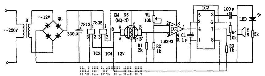
The circuit consists of a buck rectifier and voltage regulator, a gas sensor, a comparator circuit, and an alarm sound circuit. The buck regulator circuit includes a transformer, a bridge rectifier, and components such as QL, IC3 (7812), and...
As an essential component of an advanced computer science course focused on microcomputer systems, it was determined that students would benefit from the design of a single-board computer system utilizing a widely available microprocessor. This decision led to the...
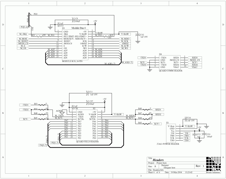
The QCard Controller Single Board Computer (SBC) features the Freescale 68HC11 microcontroller, along with RAM and Flash memory, digital input-output (I/O), and analog-to-digital (A/D) conversion capabilities. For comprehensive details regarding the QCard headers mentioned on this page, refer to...
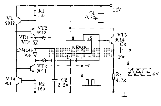
The circuit depicted involves transistors VT1, VT2, and resistor R1, which form a constant current source for charging capacitor C2 in a linear manner. Transistors VT3, VT4, and resistor R2 create a constant current source for discharging capacitor C2,...