
Ultra Low Current Oscillator

The unijunction transistor (UJT) relaxation oscillator circuit typically consists of two transistors: one PNP and one NPN. The PNP transistor is configured to provide a stable reference voltage, while the NPN transistor acts as the switching element. The circuit relies on the charging and discharging of the capacitor, which is key to generating oscillations.
In this configuration, the 100pF capacitor is charged through the 1GΩ resistor, creating a time constant that determines the frequency of oscillation. The charging process continues until the voltage across the capacitor reaches a threshold level sufficient to forward bias the base-emitter junction of the NPN transistor. This forward biasing leads to a rapid increase in collector current, which subsequently discharges the capacitor quickly, causing the voltage to drop.
Once the capacitor discharges below a certain level, the NPN transistor turns off, and the cycle repeats. The frequency of oscillation can be adjusted by varying the capacitance or resistance values in the circuit. This type of oscillator is often used in applications requiring low-frequency square wave signals, such as in timing circuits, tone generation, and clock pulses for digital circuits.
The overall behavior of the circuit can be analyzed using the time constant formula τ = R × C, where τ is the time constant, R is the resistance, and C is the capacitance. The resulting oscillation frequency can be approximated by the formula f = 1 / (2πτ), allowing for precise control over the output frequency by selecting appropriate component values.The circuit functions like a unijunction transistor relaxation oscillator. The base of the lower PNP transistor is biased at roughly half supply. As the 100pF capacitor is charged up through the 1G resistor, the base of the upper NPN transistor reaches a critical voltage, which begins to forward bias the base-emitter junction . 🔗 External reference
Related Circuits
A detailed discussion on implementing current limiting or foldback current limiting for the linear regulator controllers of the MAX1864. This can also be applied to other discrete regulator designs, including the MAX1865, MAX1964, MAX1965, MAX8513, and MAX8514. To incorporate current...
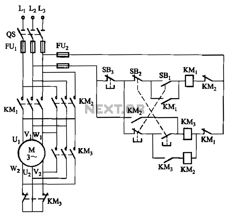
A hoist rated at 22kW and below is equipped with a power-saving Y-conversion circuit, as depicted in the figure. This circuit enhances the standard hoist design by incorporating a CJ20-10A exchange contactor. The implementation of the Y-conversion circuit during...
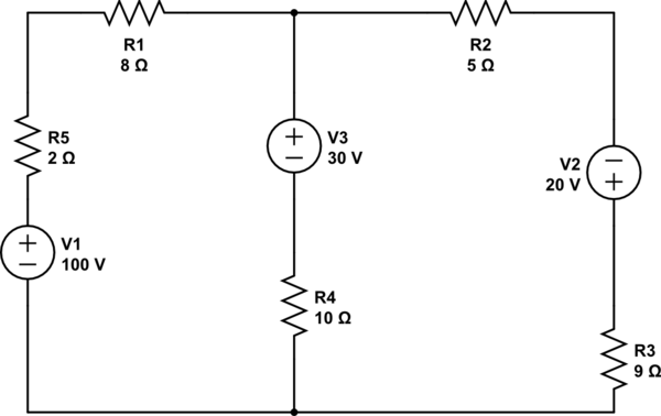
Using the superposition theorem, it is necessary to determine the current at all three nodes of the circuit. The current from the source, denoted as i_1, represents the current through V1 when other voltage sources are shorted out, in...
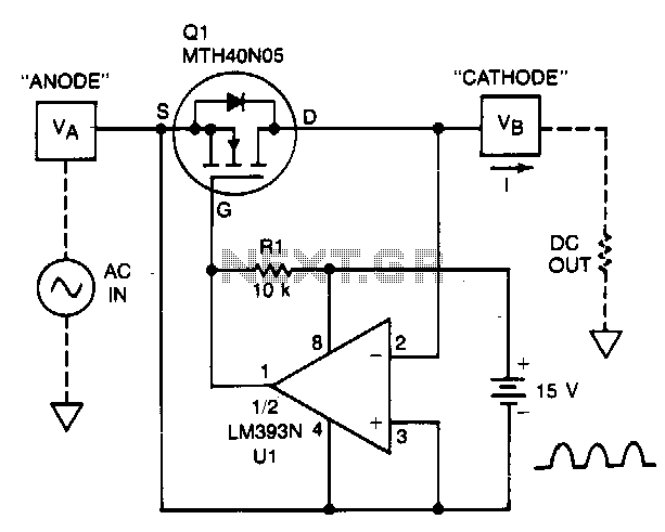
A TMOS power FET, Q1, and an LM393 comparator provide a high-efficiency rectifier circuit. When voltage V1 exceeds V2, the output of U1 becomes high, and Q1 conducts. Conversely, when V2 exceeds V1, the comparator output becomes low, and...
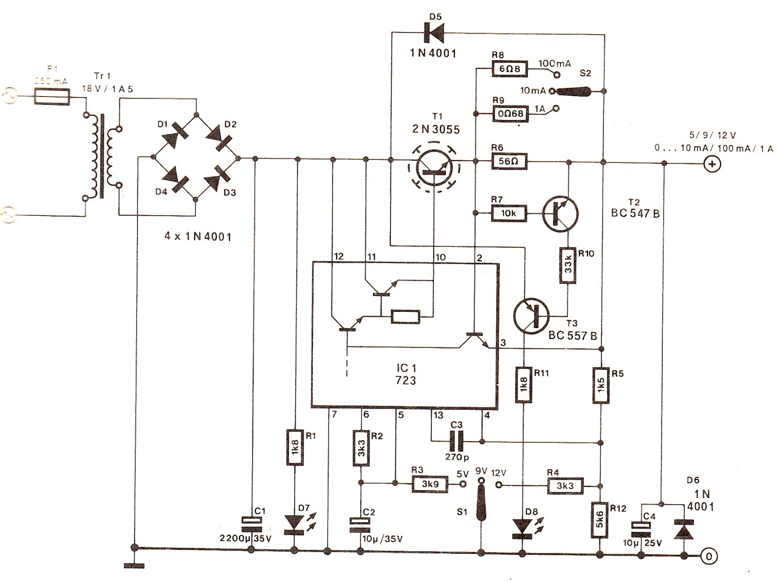
The output voltage can be increased easily by placing a resistor in parallel with Ra until it reaches precisely 5.0 V. Switches S1 and S2 are preferably SPDT types with a center position, but three-way rotary switches can also...
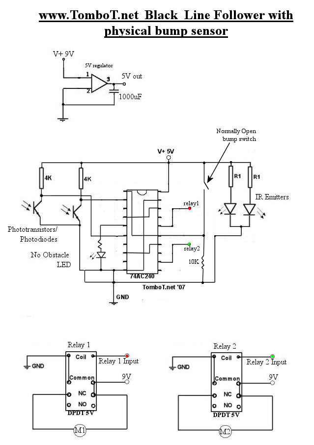
The motors will be powered by the full source voltage, so it is important to ensure that this does not cause the robot to operate too quickly. The Firebot utilizes GM3 motors powered by a 9V battery; however, in...