
High Frequency Generator Circuit

The high-frequency waveform generator circuit typically employs operational amplifiers (op-amps) or specialized waveform generator ICs to create various waveforms. The core of the circuit consists of a feedback loop that determines the frequency and amplitude of the output signal.
To generate a sine wave, the circuit may utilize a Wien bridge oscillator configuration, which includes resistors and capacitors to set the frequency while maintaining stability. The output can be adjusted using variable resistors or potentiometers to fine-tune the amplitude and frequency of the sine wave.
For generating triangle and square waves, the circuit can incorporate a Schmitt trigger or a comparator. By feeding the output of the sine wave generator into the comparator, the circuit can produce a square wave by switching the output high and low at the peak and trough of the sine wave. To create a triangle wave, an integrator circuit can be used in conjunction with the square wave output, converting the square wave into a linear ramp signal.
The power supply for this circuit typically requires a dual supply voltage to accommodate the op-amps or waveform generator ICs, ensuring that the output can swing positively and negatively around a reference point. Proper decoupling capacitors should be placed close to the power supply pins of the components to filter any noise and ensure stable operation.
Overall, this high-frequency waveform generator circuit offers versatility and adaptability for various electronic applications, making it an essential tool for engineers and hobbyists alike.This is a design circuit for high frequency waveform generator is very useful in electronic experiment and design. This circuit is generate sine wave oscillation, but actually we can modify the circuit to generate triangle or square wave function.
Th .. 🔗 External reference
Related Circuits

The circuit utilizes a dual operational amplifier integrated circuit (IC), specifically the 1458, which contains two separate op-amps within a single package. In this configuration, the first op-amp functions as a voltage follower, directing its output to charge capacitor...
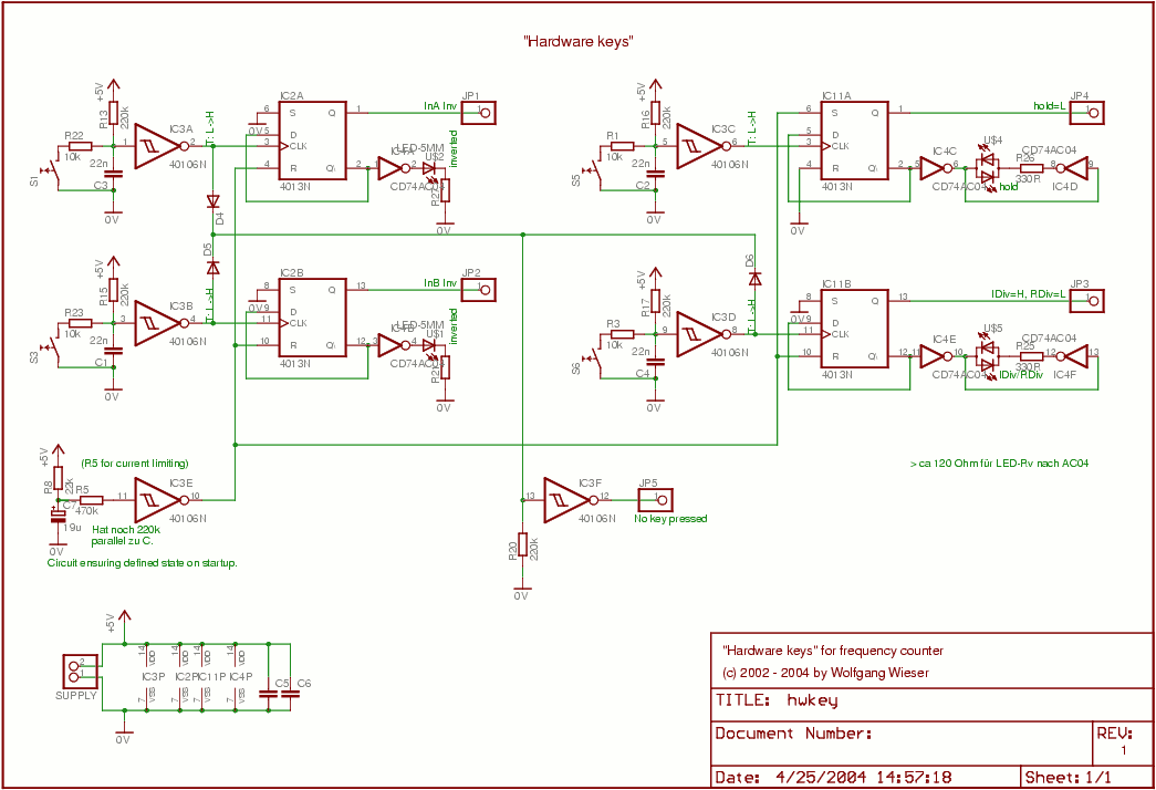
This circuit consists of four nearly identical debounced switches. Each switch features two resistors and one capacitor at the input of its respective Schmitt trigger, which are utilized for debouncing. The output from the Schmitt triggers is directed into...
The VTG-01 is designed to display user defined text over a composite video signal. This is useful in a multitude of different applications such as adding titles to home movies and adding custom text to security videos. Text can...
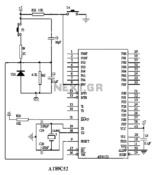
The American Atmel AT89C52 is a low-voltage, high-performance CMOS 8-bit microcontroller chip that contains 8KB of rewritable program memory and 256B of random access data memory (RAM). Atmel's high-density devices utilize non-volatile memory technology and are compatible with the...
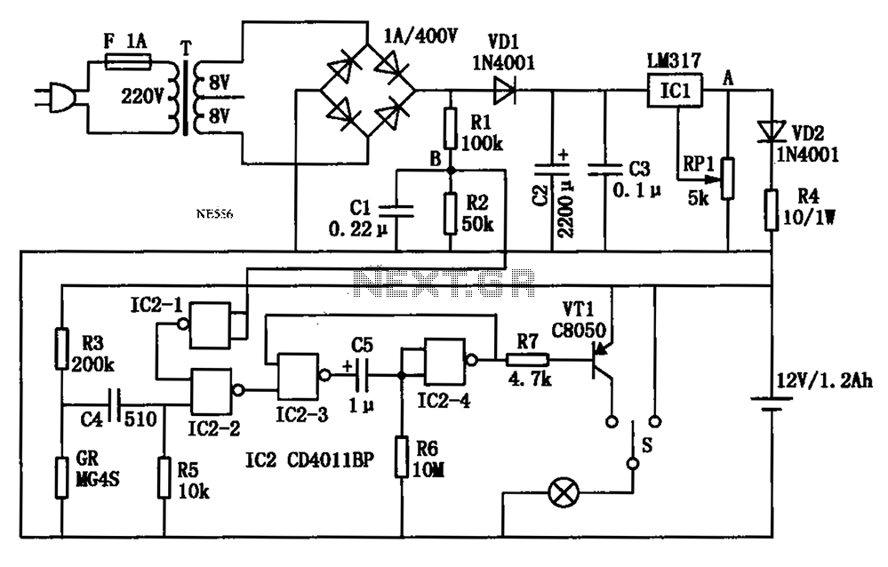
An automatic multipurpose emergency lights circuit is presented. Typically, emergency lights are connected to the mains for standby when fully charged. In the event of a sudden power failure, the ambient light transitions from strong to weak, indicating a...
The thyristor AC switch circuit is not triggered, due to its simplicity, cost-effectiveness, and non-contact operation, making it widely utilized. The circuit is illustrated in Figure 16-43. It consists of single-phase thyristor switching circuits. Figure 16-43 (a) depicts a...