
High Frequency Waveform GeneratorCircuit

The high-frequency waveform generator circuit utilizes the MAX038 integrated circuit, which is designed for generating various waveform outputs with a significant frequency range. The circuit architecture typically includes a few key components: the MAX038 IC, resistors, capacitors, and a power supply. The IC features multiple output pins, allowing for sine, triangle, and square wave outputs, which can be selected and modified based on the circuit configuration.
To achieve frequency modulation, the circuit employs a resistor (RIN) connected to the reference pin (pin 1) of the MAX038. By replacing this resistor with a DAC, the frequency can be adjusted dynamically through digital control. This allows for precise frequency settings, which is particularly useful in applications requiring specific waveform characteristics. The DAC can be interfaced with a microcontroller, enabling easy programming and control over the waveform parameters.
Furthermore, the PLL functionality can be implemented by connecting a quartz crystal oscillator to the circuit. This setup enhances the frequency stability and accuracy of the waveform generated. The phase comparator within the circuit compares the output frequency from the MAX038 with the reference frequency from the quartz crystal, allowing for fine-tuning of the output waveform. This feedback mechanism ensures that the output frequency remains consistent, even with variations in supply voltage or temperature.
The MAX038's ability to generate frequencies from 0.1 Hz to 20 MHz makes it suitable for a wide range of applications, including signal testing, modulation experiments, and audio signal generation. The versatility of this waveform generator circuit makes it an essential tool in both educational and professional electronics environments, facilitating a deeper understanding of waveform generation and manipulation.High frequency waveform generator is very useful in electronic experiment and design. This circuit generate sine wave oscillation, but actually we can modify the circuit to generate triangle or square wave function. The frequency can be controlled using current. If we disconnect the 20k RIN from REF (pin 1) and connect it to a DAC, then we can con trol the frequency using microcontroller or digital interface. We can even control the chip using a quartz crystal (PLL) by controlling the current using a phase comparator output that compares the sync output (pin 14 of MAX038) and a reference clock from quartz crystal oscillator. This waveform generator integrated circuit chip is very interesting since it can generate 0. 1Hz to 20MHz, very wide operating frequency, as expected for every waveform generator instruments. 🔗 External reference
Related Circuits
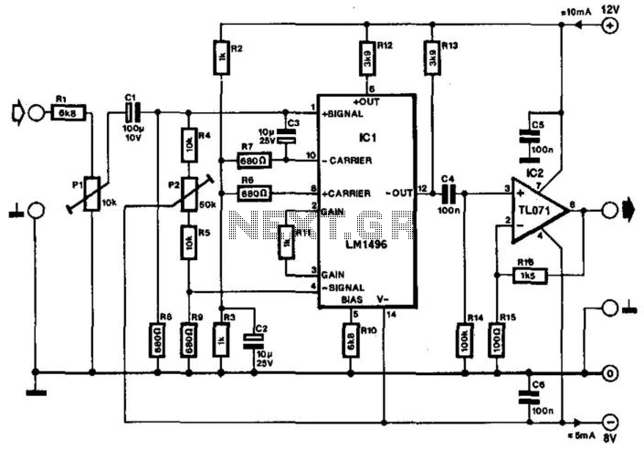
Often, the frequency of a signal must be doubled, and the modulator/demodulator chip LM1496 serves as an ideal basis for this application. From trigonometry, it is well known that 2sin(x)cos(x) = sin(2x) and sin^2(x) = 1 - cos^2(x). These...
As power supply switching frequencies increase, higher loop crossover frequencies are necessary to keep pace with the escalating load transient slew rate demands and to reduce the number and size of filter components. For voltage-mode-controlled supplies, the voltage loop...
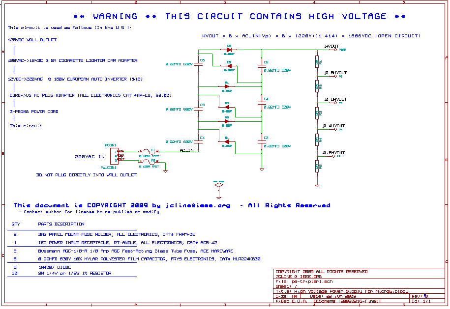
This high voltage, low current power supply has been designed for various experiments in systems and synthetic biology. The schematic and board layout are provided below. The circuit can output up to +1,866 VDC at under 1 mA and...
With the advancement of technology and the widespread use of large high-accuracy dynamic range D/A converters for full-speed digital signal processing, the generated frequency remains relatively fixed due to the phase control achieved through digital means and adjustable synthesis...
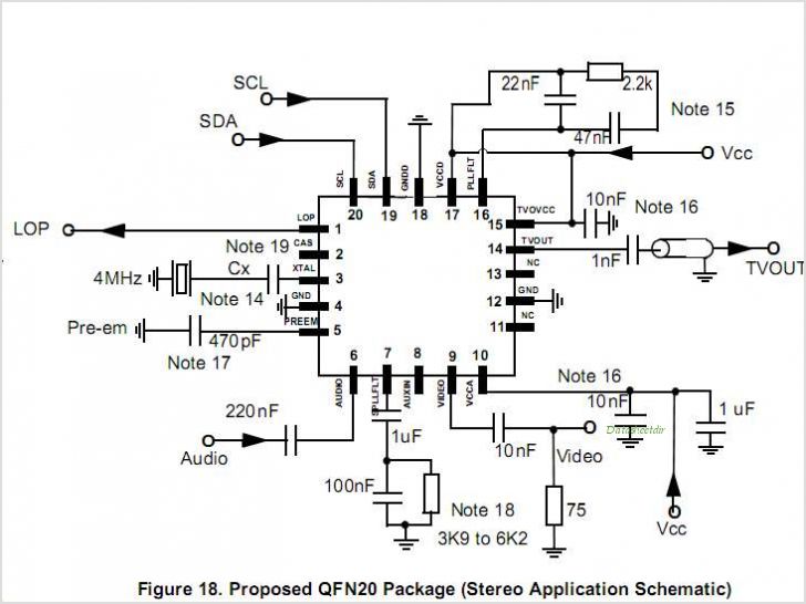
MC44BS374CA: PLL Tuned UHF and VHF Audio Video High Integration Modulator MC44BS374CA The MC44BS374CA Audio and Video Modulator is for use in VCRs, set-top boxes, and similar devices. By Freescale Semiconductor, Inc The MC44BS374CA is a highly integrated audio and...

This design circuit is a tachometer circuit based on the LM2907 integrated circuit, which can provide zero-crossing data to a digital system. At each zero crossing of the input signal, the charge pump alters the state of capacitor C1...