
Low Cost High Voltage Power Supply

The operational procedure involves resuspending pelleted bacterial cells in 250 µl of Buffer P1, ensuring that RNase A is included, and confirming that no cell clumps are visible after resuspension. If LyseBlue reagent is added to Buffer P1, it is essential to shake the buffer bottle vigorously to dissolve the particles completely. Complete resuspension of the bacteria is achieved by vortexing or pipetting until no clumps remain. Following this, 250 µl of Buffer P2 should be added and mixed thoroughly by inverting the tube 4 to 6 times without vortexing, as this could lead to undesirable results.
The prototype project highlights the potential for automation in biological protocols, suggesting that a machine could learn to execute these tasks autonomously, thus bridging the gap between biology and engineering.
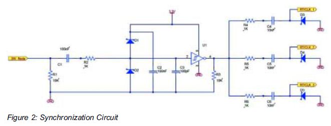
The high voltage, low current power supply circuit is designed with multiple stages to achieve different output voltages. The core of the design comprises a high-voltage transformer and a rectification stage that converts AC voltage to DC. The output voltage can be adjusted by selectively bypassing certain stages of the circuit, allowing for versatility in laboratory applications.
The circuit includes safety features to prevent over-voltage and current conditions, which are critical when working with high-voltage supplies. Components such as high-voltage capacitors and resistors are selected based on their voltage ratings, ensuring they can handle the output without failure.
In practical applications, this power supply can be utilized in experiments that require precise voltage control, such as in electrochemistry or electrophoresis. The capability to output varying voltages makes it suitable for a range of experiments, from simple DIY projects to complex institutional research.
The schematic also indicates the layout of the circuit board, which is essential for ensuring proper connections and minimizing noise. The board layout is designed to facilitate efficient routing of high-voltage traces, with careful attention to spacing to prevent arcing and ensure safety during operation.
This power supply prototype exemplifies the integration of electronics in biological research, showcasing how engineering solutions can enhance experimental methodologies in synthetic biology and related fields.I have designed this high voltage, low current power supply for various experiments in systems & synthetic biology. I have cleaned up the design and I am placing the schematic and board layout online below! This circuit outputs up to +1, 866VDC at under 1 mA or can be tapped at various points for +622VDC or +933VDC.
This is useful for either DIY Bi ology or institutional research experiments such as: Below is the schematic; read the full post below for the board layout information. Click on the schematic for the full sized version. The schematic operates in stages, so leaving out or bypassing before the 2nd final stage will yield only +933VDC, and leaving out that stage will yield only +622VDC, etc.
Imagine reading these kinds of instructions and performing such a task for a few hours: Resuspend pelleted bacterial cells in 250 µl Buffer P1 and transfer to a micro-centrifuge tube. Ensure that RNase A has been added to Buffer P1. No cell clumps should be visible after resuspension of the pellet. If LyseBlue reagent has been added to Buffer P1, vigorously shake the buffer bottle to ensure LyseBlue particles are completely dissolved.
The bacteria should be resuspended completely by vortexing or pipetting up and down until no cell clumps remain. Add 250 µl Buffer P2 and mix thoroughly by inverting the tube 4 6 times. Mix gently by inverting the tube. Do not vortex, as this will result in (The protocol examples used here are from Qiagen`s Miniprep kit, QIAPrep.
) Wait a minute! Isn`t that what robots are for Unfortunately, programming a bioscience robot to do a task might take half a day or a full day (or more, if it hasn`t been calibrated recently, or needs some equipment moved around). If this task has to be performed 100 or 10, 000 times then it is a good idea to use a robot. If it only has to be done twice or 10 times, it may be more trouble than it`s worth. Is there a middle ground here If regular English-language biology protocols could be fed directly into a machine, and the machine could learn what to do on it`s own, wouldn`t that be great What if these biology protocols could be downloaded from the web, from a site like protocol-online.
org It`s possible! (Within the limited range of tasks that are required in a biology lab, and the limited range of language expected in a biology protocol. ) The point of this prototype project is this: there are thousands of biology protocols in existence, and biologists won`t quickly transition to learning enough engineering to write automated language themselves (and it is also more effort than should be necessary to use a easy-to-use GUI for training a robot).
The computer itself should be used to bridge the language gap. Microfluidics automation platforms (Lab on Chip) may be able to carry out the bulk of busy work without excessive training required. 🔗 External reference
Related Circuits
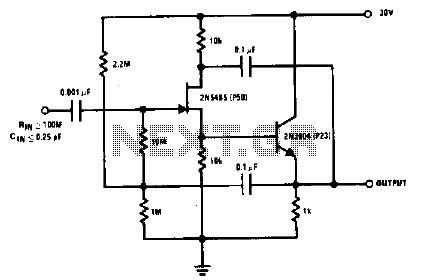
The 2N5485, which has a very low-capacity legacy, is always operated as a source follower with gate bias bootstrap. In this circuit, nothing is left to chance in reducing input capacitance. The 2N5485 is a JFET (Junction Field Effect Transistor)...
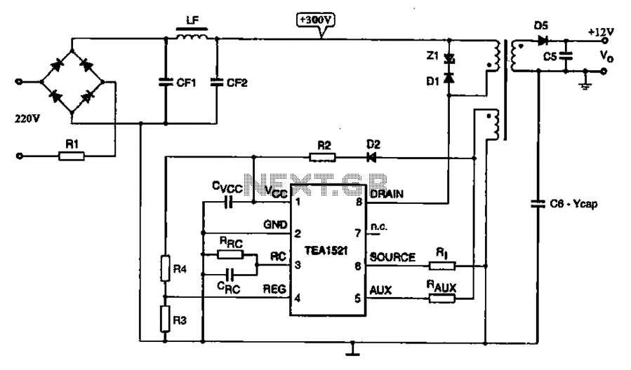
A typical DVD switching power supply circuit is shown in the standby power supply circuit of digital products. It utilizes a switching power supply structure, with the oscillation switch IC EA1623 providing oscillation pulses to the transformer. The secondary...
This chapter presents detailed schematics for various power supplies compatible with commonly available Ar/Kr ion tubes in the surplus market. It includes examples of commercial designs such as the Omnichrome 150R and 532 head, Lexel 88 and head, alongside...
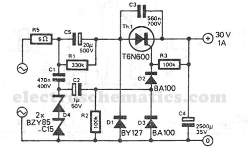
This transformerless power supply circuit is designed for medium current applications. During the negative half period, the capacitor C5 is charged to the peak voltage of the network. The positive half wave will trigger the thyristor, allowing the electric...
A Practical Application for Cyclone V FPGA Power Requirements The integration of multiple power modules on a single power board allows for specific load requirements to be met efficiently. The Cyclone V FPGA requires careful consideration of its power supply...
This low-cost DC supply voltage monitor emits a warning when the voltage drops below a specified threshold. It is particularly suitable for monitoring rechargeable batteries as it consumes only a few microamperes in its idle state. The voltage level...