
High-intensity LED Warning Flasher

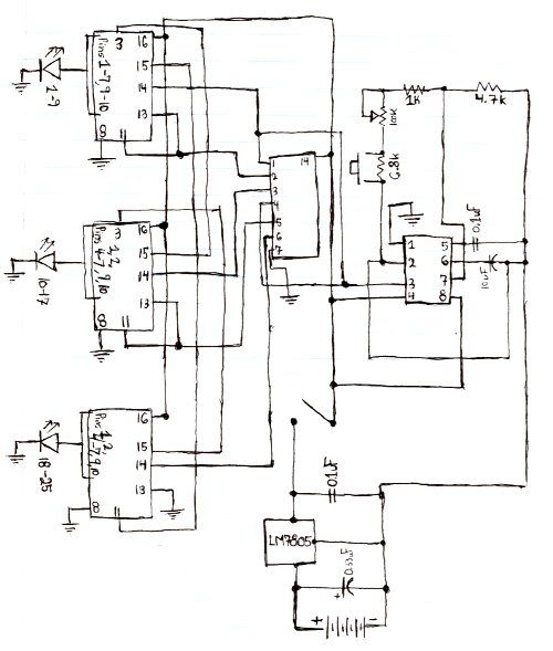
The circuit operates effectively by utilizing solar energy to charge batteries during daylight, ensuring functionality in low-light conditions. The inclusion of two 1.6-V solar cells facilitates the charging of the AA batteries, which serve as the primary power source when ambient light is insufficient. The voltage from the solar cells is rectified by diode D4, preventing reverse current flow and ensuring that the batteries receive a steady charge.
In the absence of light, PNP transistor T1 becomes active, allowing the stored energy in the batteries to power the oscillator circuit formed by transistors T2 and T3. This oscillator generates a low-frequency square wave signal that controls the timing of the LED illumination. Transistor T3, when activated, allows the collector voltage to rise, triggering the LED driver circuit involving transistor T4. The high-brightness yellow LEDs (D1 and D2) provide significant visibility, while the red LED (D3) serves as an indicator of the circuit's operational status.
The design allows for flexibility in the number of LEDs used, enabling customization based on brightness requirements. However, caution must be exercised to ensure that the total current drawn does not exceed the specifications of transistor T4. For applications requiring greater brightness or additional LEDs, transitioning to a MOSFET transistor is advisable, as it can handle higher current loads more efficiently than traditional bipolar junction transistors like the BC547B.
Overall, this circuit is a practical solution for enhancing visibility in low-light conditions, making it suitable for various applications, including as a warning device for vehicles and as a safety feature for bicycles.This circuit was designed as a warning flasher to alert road users to dangerous situations in the dark. Alternatively, it can act as a bicycle light (subject to traffic regulations and legislation). White LEDs only are recommended if the circuit is used as a bicycle front light (i. e. for road illumination) and red LEDs only when used as a tail lig ht. During the day, the two 1. 6-V solar cells charge the two AA batteries. In darkness, the solar cell voltage disappears and the batteries automatically power the circuit. The flash frequency is about one per second and the LED on-time is about 330 ms. The duty cycle should enable the batteries to power the circuit over night. The circuit is composed of three parts. Under normal daylight conditions the batteries are charged through diode D4. In darkness, pnp transistor T1 is switched on, supplying battery current to the second part, a low-frequency oscillator comprising T2 and T3. The third part is the LED driver around T4. It conducts and switches on the LEDs D1-D2-D3 when the collector voltage of T3 swings high. Two LEDs (D1, D2) are 20, 000-30, 000 mcd high-brightness yellow types and one (D3) is a normal 3-mm red LED for control purposes.
Of course it is possible to increase the number of LEDs to obtain higher brightness. However you will run into limitations regarding the maximum collector current of transistor T4. For really high power applications a MOSFET transistor is suggested instead of the common or garden BC547B. 🔗 External reference
Related Circuits

In this project it was used the Piranha Super-flux RGB Led of common anode, and the PIC18F25K20, in order to generate combinations of colors. It has two function modes, automatic that generate the color sequence that is stored in...
Here is the schematic for the circuit. Solder all the components onto a perfboard. The drawings may not be very clear. Essentially, the 555 timer generates a pulse. The circuit utilizes a 555 timer IC configured in astable mode, which...

This is a simple toggle switch that can be operated through sound signals such as a whistle or clap. The output of the toggle remains either low or high until... This circuit utilizes a sound sensor to detect specific audio...
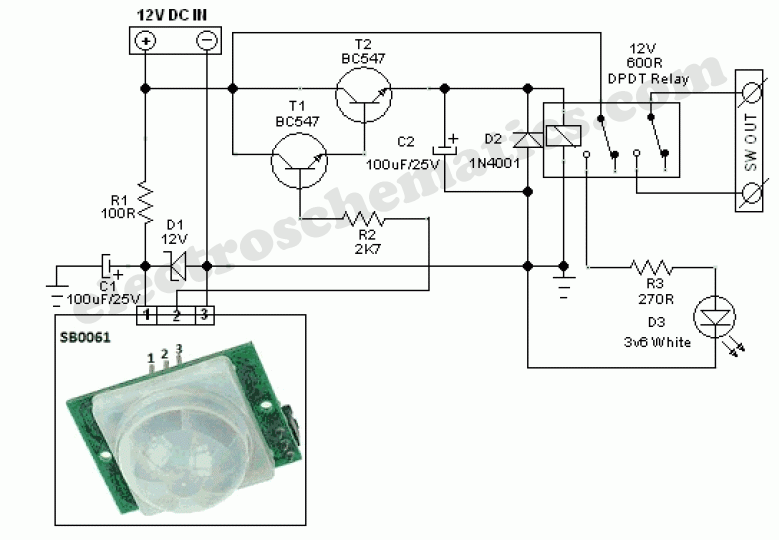
This circuit represents a general-purpose white LED security light equipped with a Passive Infrared (PIR) motion sensing mechanism. The core component of the circuit is the PIR sensor module SB0061, which is a pyroelectric sensor designed for human body...
The schematic below illustrates a simple LED flasher circuit. This circuit utilizes three LEDs that begin to blink or flash upon receiving a 9-volt supply. It is straightforward in design, employing a self-flashing LED (LED 1) to trigger the...

All LED negatives are connected to the "COM" pad, then through a 220 Ohm resistor to ground. There is no need for additional current limiting resistors, even with supply voltages up to 16 volts. The described circuit employs a simple...