
LED CHASER Sequencer

The described circuit employs a simple yet effective design for LED connections. In this configuration, the negative terminals of all LEDs are tied to a common pad labeled "COM," which serves as a reference point for the LED circuit.
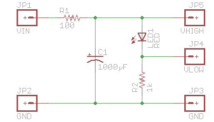
The current limiting is achieved using a single 220 Ohm resistor, which is connected from the "COM" pad to ground. This resistor ensures that the current flowing through the LEDs remains at a safe level, preventing damage due to excessive current. The choice of a 220 Ohm resistor is suitable for a wide range of supply voltages, up to 16 volts, allowing for versatility in applications without the need for additional resistors for each LED.
When the circuit is powered, the voltage across each LED will depend on the forward voltage drop characteristic of the specific LED used, which typically ranges from 1.8V to 3.3V for standard LEDs. The remaining voltage, after accounting for the forward voltage drop, will be dropped across the 220 Ohm resistor, thereby controlling the current through the LEDs.
This design is particularly advantageous in applications where multiple LEDs are used, as it simplifies the circuit layout and reduces component count. The absence of additional current limiting resistors for each LED not only minimizes space on the PCB but also enhances reliability by reducing the number of potential failure points.
In summary, this LED circuit design is efficient, cost-effective, and suitable for various applications, providing effective current regulation while maintaining simplicity in construction.All LED`s Negatives are a connection to the "COM" pad, than through a 220 Ohm resistor to Ground. No Need for other "current limiting" resistors, even with supply voltages up to 16 volts. ) 🔗 External reference
Related Circuits
Trigger circuit routing forms include various types such as simple trigger circuits, single-junction transistor trigger circuits, synchronous sine wave trigger circuits, sawtooth transition phase shift (synchronous) trigger circuits, and integrated trigger circuits. This section presents individual cases for introduction...

Transmitter RF Output LED Indicator Circuit Diagram. This RF output detector circuit, which includes a visual indicator, can be useful for an RF application. The transmitter RF output LED indicator circuit is designed to provide a visual representation of the...

This circuit is usable as a Night Lamp when a wall mains socket is not available to plug-in an ever running small neon lamp device. In order to ensure minimum battery consumption, one 1.5V cell is used, and a...
It is sufficient to explore PWM (Pulse Width Modulation) and digital-to-analog conversion, illustrating how to create a personal electronics workbench for investigating RC (Resistor-Capacitor) filters, charge and discharge curves, pulse generators, timers, and even a simple oscilloscope to understand...
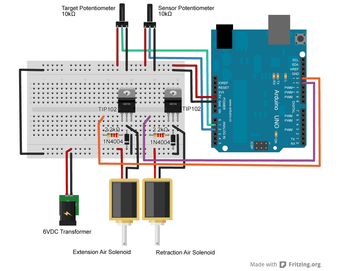
For an upcoming project, a pneumatic ram with a closed-loop control system was required to achieve precise positioning. Due to budget constraints, an off-the-shelf solution was not feasible, prompting the assembly of a custom system using an Arduino, a...

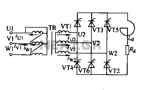
Adjusting the phase potentiometer RP can change the conduction angle of each corresponding thyristor (V1-V). This adjustment alters the voltage applied across the load. The circuit utilizes a phase control technique to manage the power delivered to a load by...