
solar flasher

The described circuit operates as a Joule Thief, a type of boost converter that utilizes a single transistor to extract energy from a low-voltage power source, such as a depleted battery. The addition of a third coil to the circuit enhances its functionality by allowing for greater energy storage and improved output characteristics.
In this configuration, the primary coil is responsible for initiating magnetic flux when a voltage is applied to the base of the transistor, turning it on. As the transistor conducts, current flows through the primary coil, creating a magnetic field. When the transistor turns off, the collapsing magnetic field induces a voltage in the secondary coil, which can be used to power a load. The introduction of the third coil serves to capture and store more energy during the flyback period, effectively increasing the duration and intensity of the output flash.
The circuit can be constructed using minimal components: a transistor (commonly an NPN type), resistors for biasing, and the three coils (primary, secondary, and the additional coil). The absence of large capacitors simplifies the design and reduces the overall size and cost of the circuit while still achieving high efficiency and enhanced performance.
This configuration is particularly useful in applications requiring brief but intense bursts of light, such as in flashlights or camera flashes, where the increased brightness and duration are crucial. The careful selection of coil windings and the number of turns can further optimize the circuit's performance, allowing for fine-tuning based on specific application needs.This circuit is a single transistor flyback (Joule Thief) circuit that features a third coil. With it, flash duration and brightness is much enhanced, without resorting to large value capacitors. 🔗 External reference
Related Circuits
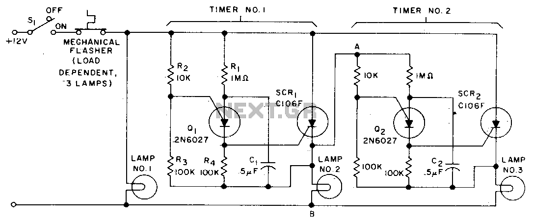
When the turn signal switch (SI) is closed, lamp #1 is activated, and capacitor C1 charges to the triggering voltage of transistor Q1. Once the anode voltage on Q1 exceeds its gate voltage by 0 V, Q1 transitions to...
The LED flasher circuits operate on a single 1.5-volt battery. The circuit on the upper right utilizes the widely used LM3909 LED flasher integrated circuit (IC) and requires only a timing capacitor and an LED. The LM3909 is a specialized...
These are small lights with a stake on the bottom that can be inserted into the ground along driveways or sidewalks, featuring a solar panel on top. The solar cell charges a AA NiCd battery during the day, and...
This is a 200W lamp flasher circuit diagram. The frequency of the lamp flashing can be adjusted within a range of 1Hz to 5Hz using the PR1 variable resistor (trimpot). The duty cycle of the lamp flashing can be...
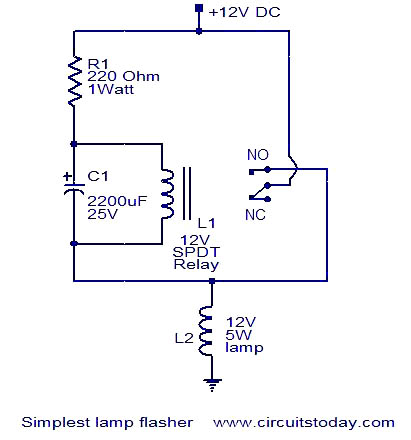
This is a simple lamp flasher circuit that utilizes only three components (a capacitor, a relay, and a resistor) in addition to the lamp. The operation of the circuit is straightforward. When power is turned on, the capacitor C1...
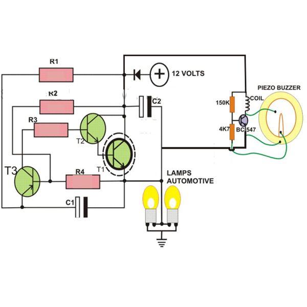
This circuit is designed to create a flasher unit for a motorbike. It is a simple turn signal flasher circuit that can be easily built and installed in any two-wheeler for the desired functionality. The circuit uses only two...