
High Performance Audio Power Amplifier schematics Circuit using LM3886

The LM3886 is a high-performance audio power amplifier IC designed to deliver high-quality sound reproduction with low distortion. It is capable of providing a maximum output power of 68 watts into an 8-ohm load and can handle a wide range of supply voltages, typically between 10V to 30V. The circuit configuration often includes a few essential components like resistors, capacitors, and inductors that work together to optimize performance.
The typical schematic for an LM3886 audio power amplifier includes the following key elements:
1. **Power Supply**: The circuit requires a dual power supply, providing both positive and negative voltages. This is essential for the amplifier to handle both halves of the audio waveform effectively.
2. **Input Stage**: The input stage generally consists of a coupling capacitor to block DC voltage and protect the source device, followed by a resistor network that sets the gain of the amplifier. The gain can be adjusted by changing the feedback resistors connected between the output and the inverting input.
3. **Feedback Network**: The feedback network plays a critical role in stabilizing the amplifier and minimizing distortion. It typically consists of resistors and capacitors that define the frequency response of the amplifier.
4. **Output Stage**: The output stage is where the amplified signal is delivered to the speaker. The LM3886 includes built-in thermal protection and short-circuit protection, which enhances reliability during operation.
5. **Decoupling Capacitors**: These capacitors are placed near the power supply pins of the LM3886 to filter out any high-frequency noise that may affect the performance of the amplifier.
6. **Protection Circuitry**: Additional components may be included to protect against over-voltage and over-current conditions, ensuring the longevity and reliability of the amplifier.
In summary, the LM3886 audio power amplifier circuit schematic is a sophisticated design that incorporates various elements to provide high-quality audio amplification. Proper implementation of this circuit can significantly enhance the performance of audio systems, making it a popular choice among audio enthusiasts and professionals alike.Circuit LM3886 High Performance audio Power amplifier schematics Circuit Electronics, Audio Power amplifier is an important part in sound reproduction ina sound system. audio Power amplifier with this power IC LM 3886Audio Power amplifier.. 🔗 External reference
Related Circuits
A JFET-bipolar cascode circuit is designed to deliver complete video output for driving the cathode of a CRT. The configuration offers an approximate gain of 90. The cascode arrangement mitigates issues related to the Miller capacitance of the JFET...
60W Bass Amplifier. It features low-cut and bass controls. The output power is 40W on 8 Ohm loads and 60W on 4 Ohm loads. An amplifier circuit diagram is provided. The 60W bass amplifier is designed to deliver robust audio...
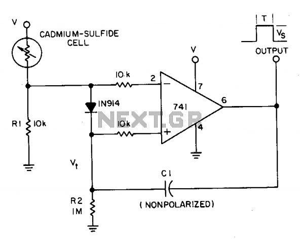
A photocell circuit provides automatic threshold adjustment. Monostable action prevents undesired retriggering of the output. With only one op amp IC, the circuit offers automatic adjustment of its trigger level to accommodate various light sources, changes in ambient light,...
This low-noise microphone amplifier is built with the MAT02 produced by PMI. This microphone amplifier is highly efficient and features a very low noise level. The amplification can be set to either 20 dB or 23.5 dB (10x or...
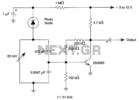
The circuit utilizes a tuned circuit for frequency selection, designed to operate at approximately 51 kHz. The 2N3565 transistor amplifies the output generated by the tuned circuit. The described circuit operates on the principle of resonance, where the tuned circuit...
A schematic of a flip-flop LED flashing circuit is presented. This circuit functions as an astable multivibrator that activates LEDs sequentially upon power application. It is compatible with voltage inputs ranging from 6 to 12 volts, and can also...