
60W Bass Amplifier

The 60W bass amplifier is designed to deliver robust audio performance tailored for low-frequency sounds, making it ideal for bass instruments and music genres that emphasize bass. The amplifier incorporates low-cut and bass controls, allowing users to adjust the frequency response to suit their preferences and the acoustics of the environment.
The output power specifications indicate that the amplifier can deliver 40W when connected to an 8 Ohm load, which is typical for many speaker configurations. When connected to a 4 Ohm load, the amplifier can produce a maximum output of 60W, providing increased power for more demanding applications or larger speaker setups.
The circuit design of the amplifier is critical to its performance. It typically consists of a preamplifier stage, which processes the audio signal before it is amplified, and a power amplifier stage, which drives the speakers. The low-cut control is likely implemented using a high-pass filter, which removes unwanted low-frequency signals that may muddy the sound. The bass control may employ a variable gain stage or a shelving filter to enhance low-frequency output selectively.
In terms of component selection, high-quality capacitors and resistors are essential for maintaining signal integrity and minimizing distortion. The use of a robust power supply is also crucial, as it must provide sufficient current to handle the dynamic demands of bass frequencies without introducing noise or sagging voltage.
The amplifier's schematic diagram would typically include the layout of these components, interconnections, and any additional features such as protection circuits to prevent damage from overload or short circuits. Overall, the 60W bass amplifier is engineered to deliver powerful, clear sound reproduction, making it suitable for both live performances and studio applications.60W Bass Amplifier. Low-cut and Bass controls Output power: 40W on 8 Ohm and 60W on 4 Ohm loads Amplifier circuit diagram: Amplifier. 🔗 External reference
Related Circuits
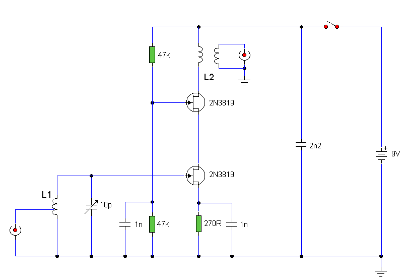
The circuit utilizes two 2N3819 FETs arranged in a cascode configuration. The lower FET functions in common source mode, while the upper FET operates in common gate mode, achieving full high-frequency gain. The lower FET is adjustable, enabling tuning...
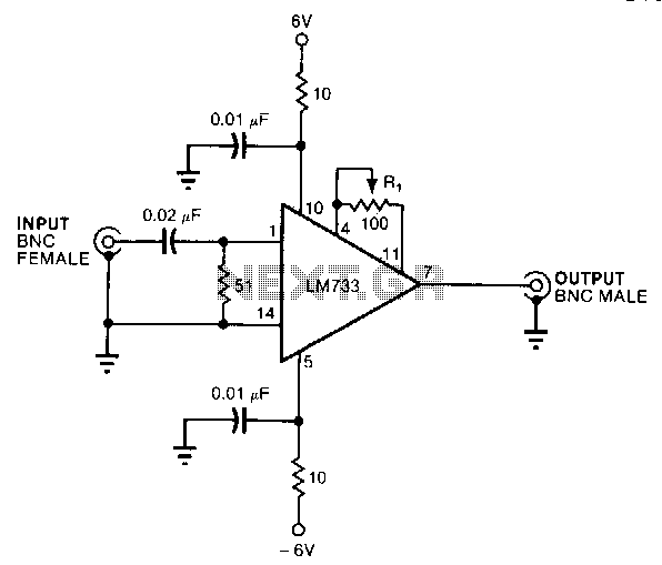
This circuit provides a voltage gain of 20 ±0.1 dB from 0.5 to 25 MHz and ±3 dB from 70 kHz to 55 MHz. An LM733 video amplifier offers a low input noise specification, with a typical value of...
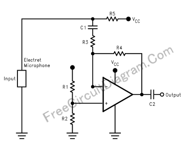
This document presents a schematic diagram of an electret microphone pre-amplifier utilizing the LMV721 operational amplifier. The LMV721 is chosen for its low noise and low power characteristics. The electret microphone pre-amplifier circuit is designed to amplify the weak audio...
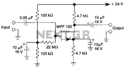
In this amplifier circuit, the gate of the MPF 102 is biased with an external voltage. This circuit achieves tighter control of the operating point and biasing conditions. The amplifier circuit utilizing the MPF 102 field-effect transistor (FET) is designed...
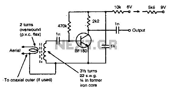
This simple circuit provides a gain of 15 dB and can be mounted on a 1 inch by 2 inch PCB. Coil specifications are provided for a frequency range of 85 to 95 MHz. For other frequencies, the coil...
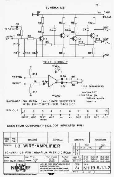
The L3 Wire Amplifier, type NH19-6112, designed by P. Rewiersma at Nikhef-H Amsterdam in February 1986, outlines the design considerations and performance of a hybrid linear amplifier for the muon detector in the LEP L3 experiment. The amplifier utilizes...