
High-performance automatic water level controller circuit

The described circuit utilizes an RS flip-flop to control the operation of a water pump based on the water level in a tank. The system is designed to ensure efficient operation while preventing damage to the pump. The key components involved in this circuit include the RS flip-flop, which maintains the state of the pump operation, and a relay that acts as a switch to control the power supply to the pump.
When the water level in the tank drops below point F, the sensor at this level triggers the RS flip-flop, setting its Q output high. This high signal activates the relay, which in turn powers the water pump, allowing it to fill the tank. As the tank fills and the water level rises, the sensor at point 4:00 detects this increase and outputs a low signal, which resets the RS flip-flop and turns off the relay, stopping the pump.
The circuit includes additional sensors at points A and B to manage the pump's operation effectively. If the water level decreases to point A, the RS flip-flop retains its state, keeping the pump off until the water level drops below point B. At this stage, the RS flip-flop is activated again, allowing the pump to restart and refill the tank as needed.
Moreover, the system incorporates a safety feature that monitors the water level in the well. If the water level drops below point D, the RS flip-flop is reset, ensuring that the pump does not operate under low water conditions. This feature is critical for preventing damage to the pump due to running dry and also contributes to energy savings by minimizing unnecessary pump operation.
Overall, the circuit is designed to operate in a cycle that efficiently manages water levels while protecting the pump from potential damage and optimizing energy use.Circuit works: When the water tank level is lower than said point, F., F2 consisting of RS flip-flop, Q output high, relay, pump the water; when the B point dipped into the water, 6 foot F2 becomes a high level, RS flip-flop on hold, the pump continues pumping. As the water level rises, when the water level reaches "4:00, F. 1 pin goes low level, Q-ended output low, open relays, pumps stopped; when the water level dropped to A point or lower, F. L foot becomes a high level, RS flip-flop and put on hold, the water pump is still stalled, only the water level below the point B, the pump was restarted, repeat the over- process.
It is important to point out that the above process is the situation in the well water level higher than D point of condition; if the well water level falls below the point D, regardless of what state the RS flip-flops are reset, the Q output of the low-side power almost, so that the pump is stopped, to prevent idling pumps and burned, but also to save energy.
Related Circuits
This project involves a simple touch switch circuit that can also be utilized to activate a relay instead of an LED and resistor. The circuit exhibits high sensitivity due to the use of two transistors configured as a Darlington...
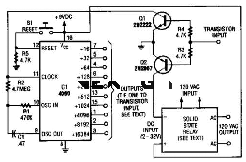
A long-duration timer can be easily constructed using a 4060 CMOS binary divider along with its integrated clock oscillator. The solid-state relay can be selected based on the specific application requirements and may be substituted with a mechanical relay...
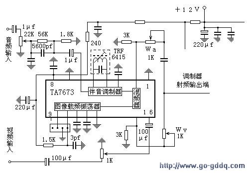
The circuit design philosophy allows for debugging without any RF instruments. Although its performance may not match that of professional equipment, it should be adequate for hobbyists, with audio-visual transmission effects comparable to general-purpose machines. The transmitter consists of...
The circuit of the unit is fairly simple, but is a bit irksome to set up. The reason is that obtaining matched FETs is not easy, so I had to make sure that the circuit would work with off-the-shelf...
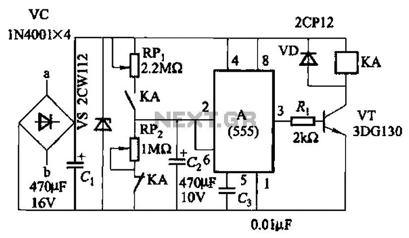
The circuit, as illustrated in Figure 3-82, employs a 555 IC to control a motor automatically, managing its start and stop cycles. The running and stopping times of the motor can be adjusted by modifying the values of potentiometers...
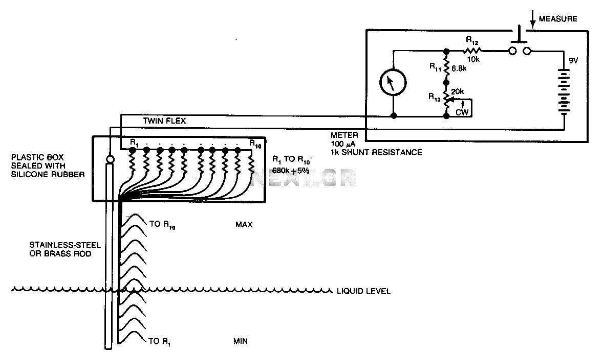
Although many circuits utilize the varying-capacitance method for measuring liquid levels, this straightforward resistive circuit is significantly easier to construct. Even a tank containing a liquid, such as water, has sufficient conductive salts in solution for this method to...