
High-performance quadrature sine wave oscillator

The RC oscillator described operates on the principles of phase shift and feedback control to generate oscillating signals. The phase shift unit typically consists of resistors and capacitors that create the necessary phase shift for oscillation. In this configuration, the voltage feedback amplifier plays a crucial role in determining the overall gain of the system. As the frequency increases, the gain of the amplifier diminishes sharply, which is a critical factor in the stability and performance of the oscillator.
The HA502 IC is designed for high-frequency applications and is well-suited for use in RC oscillator circuits. It provides a stable output and can operate effectively within a specified frequency range. In designing an RC oscillator with the HA502, careful consideration must be given to the selection of resistors and capacitors to achieve the desired oscillation frequency while maintaining adequate phase margin and gain stability.
The feedback loop in the circuit is essential for sustaining oscillation. The phase shift introduced by the RC network must equal 180 degrees at the desired frequency, and the amplifier must provide an additional 180 degrees of phase shift, resulting in a total phase shift of 360 degrees or 0 degrees, which is necessary for sustained oscillation.
Furthermore, the choice of components and their values affects not only the frequency of oscillation but also the waveform quality and output amplitude. It is important to analyze the frequency response of the circuit to ensure that the gain remains above the threshold required for oscillation across the intended frequency range.
In summary, the RC oscillator employing the HA502 IC exemplifies a sophisticated design that leverages voltage feedback amplification and phase shift techniques to generate stable oscillatory signals, albeit with inherent limitations at higher frequencies due to the amplifier's gain characteristics.Many RC oscillators use advanced circuit in phase shift unit. It uses a voltage feedback amplifier, of which the gain will get a sharp decline in a higher frequency and stop oscillation before reaching the desired frequency. That is the reason why voltage feedback amplifier has poor phase characteristics. The RC oscillator composed of high-frequency IC HA502.. 🔗 External reference
Related Circuits
Construct the Colpitts oscillator using either a breadboard (prototype board) or stripboard, and then verify its operation with a multimeter and oscilloscope. This Colpitts oscillator generates a sine wave output exceeding 12V peak-to-peak at a frequency determined by the...
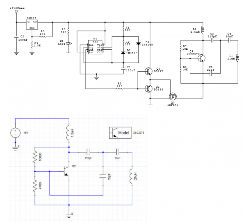
An LC oscillator is driven by pulses generated by a 555 IC-based oscillator. The LC oscillator is constructed around a 2SC2078 transistor. The circuit diagram is illustrated in Fig. 1, along with an Ansoft Designer simulation. The measured and...

In conventional triangular-wave oscillators, hysteresis from positive feedback in the Schmitt trigger determines the voltage levels and amplitude of the triangular waves. With this topology, it is difficult to independently vary the voltage levels and amplitude of the output...
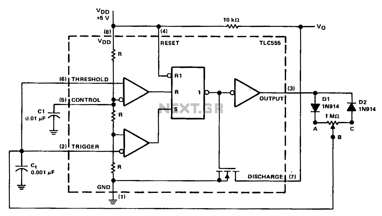
In a basic astable timer configuration, timing periods 11 and 12 are not independently controlled. This lack of control complicates the maintenance of a constant period, T, when either 11 or 12 is varied. In this circuit, the charge...
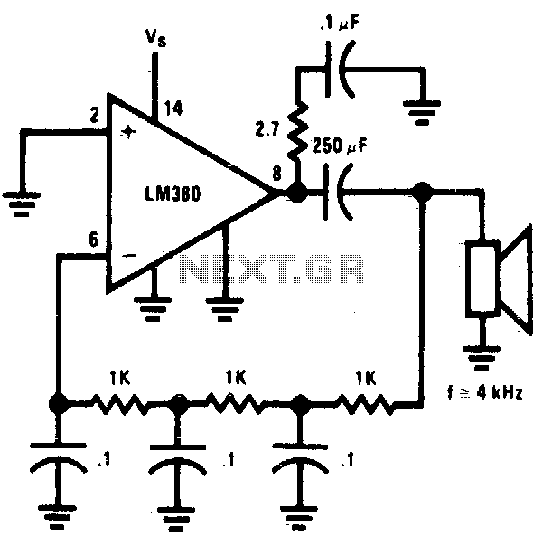
The circuit utilizes a simple RC network to generate a very high-pitched tone from a miniature speaker. With the specified component values, the circuit oscillates at a frequency of 3 kHz and drives a miniature 2W speaker at an...
This receiver is MC3371. Pin 16 is the RF input to the mixer and pin 1 and pin 2 is the local oscillator. The product comes out at pin 3. Imagine you want to receive at 100MHz. The local...