
High-performance recording front end circuit

The pre-equalizer amplifier depicted in Figure 3-17 is designed for high fidelity sound recording, integrating advanced electronic components to enhance performance while maintaining simplicity in design. The absence of mechanical switches reduces wear and potential points of failure, thereby increasing the longevity and reliability of the device. The use of electromagnetic relays allows for precise control over the circuit, making it suitable for various applications in sound recording and playback.
The editing switch feature is particularly noteworthy, as it enables the user to minimize noise during recording. This is crucial in professional sound environments where clarity and fidelity are paramount. By activating the switch during silent gaps in the audio, the system can effectively lower the noise floor, resulting in cleaner recordings.
The operational amplifier in the equalization circuit is tailored to provide necessary frequency compensation without the traditional drawbacks associated with inductive components. By eliminating complex inductor designs, the circuit not only becomes more compact but also enhances ease of adjustment, allowing for fine-tuning of sound characteristics to meet specific recording requirements. The stability of the circuit ensures that it maintains consistent performance over time, while the attention to inter-channel balance guarantees that recordings remain true to the original audio source, providing an accurate representation of sound.
This pre-equalizer amplifier is thus positioned as an effective solution for sound engineers and recording professionals seeking high-quality audio performance with reliable and user-friendly operation.Figure 3-17 is a pre-equalizer amplifier having a sound recording function has the following characteristics: (1) the circuit does not have a conventional mechanical switch cir cuit normally, instead of using a fully enclosed electromagnetic relays, this machine will go core and circuit board are mounted plane made a prerequisite, and the operational reliability of the circuit is greatly improved. Movement selected LX - 401 electronically controlled Touch movement. (2) set the editing switch, as long as the gap in the program by pressing this switch, you can make a tape of a very low noise floor.
(3) with a single recording equalization circuit operational amplifier, through a specially designed, the equalization circuit is generally not used in the circuit inductance can be high and low frequency recording compensation. Not only do design complex inductor, simplifying the electrical circuit configuration, and the circuit is stable, easy to adjust, inter-channel balance is good.
Related Circuits
This application note presents the component values and measured performance for the MAX2681 mixer IC when tuned for GPS operation at 1575 MHz. The MAX2681 is a high-performance mixer integrated circuit designed for use in GPS applications, particularly at the...
This precise one-pulse-per-second clock is constructed using a few common components and is driven by a 50 or 60 Hertz mains supply without any direct connection to it. A beep or a metronome-like click, along with a visible flash,...
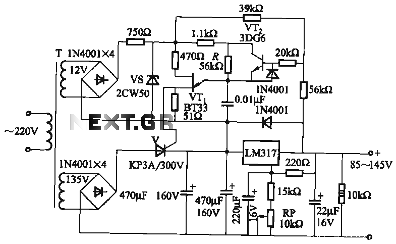
It utilizes a three-terminal adjustable voltage regulator power supply and incorporates a thyristor for presetting the LM317. The voltage can be adjusted between 85V and 145V, with an output current limited to a maximum of 1A. An adjustment potentiometer...
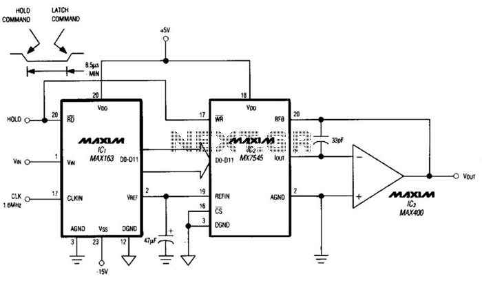
Driving a D/A converter using an A/D converter provides an overall analog-hold function. Although this function has limitations in output resolution, it offers zero voltage droop and infinite hold time. The A/D converter depicted (IC1) features a 12-bit compatible...
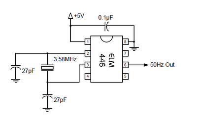
The ELM446 is an 8-pin digital divider integrated circuit that generates both 50Hz and 1Hz outputs from a common 3.58MHz NTSC colorburst crystal. The designer needs to supply only the crystal and two suitable loading capacitors, along with a...
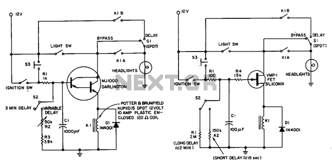
This circuit maintains the headlights of an automobile in an on state temporarily. It also ensures that the lights turn off automatically, even if the user forgets to switch them off manually. The shut-off delay is activated only when...