
High-torque motor speed control

The described circuit operates as a full-wave rectifier using a bridge configuration that is particularly effective in providing controlled power to a motor. The two SCRs function as electronic switches that can be triggered to allow current to flow through the motor in both directions, thereby enabling efficient operation.
The diodes D3 and D5 play a critical role in supplying a steady DC voltage to the trigger circuit. By utilizing dropping resistors R1, the circuit ensures that the voltage level supplied to the trigger circuit is appropriate for the operation of the UJT. This setup is essential for achieving reliable SCR firing.
The charging mechanism of capacitor C2 is crucial for controlling the timing of the SCR firing. Resistors R3 and R4 form a voltage divider that, in conjunction with zener diode D8, establishes a stable reference voltage. This reference voltage is pivotal in determining the charging rate of C2, which directly influences the phase delay of SCR firing. When the voltage across C2 reaches the threshold necessary to trigger the UJT, the UJT conducts, resulting in the firing of the corresponding SCR.
Once the SCR is triggered, current flows through the motor, and the system operates until C2 discharges below the necessary threshold. The feedback resistor Rf is integral in fine-tuning the performance of the circuit. Its value must be calculated based on the specific motor characteristics and the required feedback to maintain stable operation. A well-optimized Rf value ensures that the system can adapt to varying load conditions while maintaining efficient performance.
Overall, this bridge circuit configuration is an effective solution for controlling motor power, leveraging SCR technology and feedback mechanisms to achieve precise control over motor operation.A bridge circuit consisting of two SCRs and two silicon rectifiers furnishes full-wave power to the motor. Diodes, D3 and D5, supply dc to the trigger circuit through dropping resistors, Rl. Phase delay of SCR firing is obtained by charging C2 through resistors R3 and R4 from the voltage level established by the zener diode, D8.
When C2 charges to the firing voltage of the unijunction transistor, the UJT fires, triggering the SCR that has a positive voltage on its anode When C2 discharges sufficiently, the unijunction transistor drops out of conduction. The value of Rf is dependent upon the size of the motor and on the amount of feedback desired. A typical value for Rf can be calculated 2.
Related Circuits
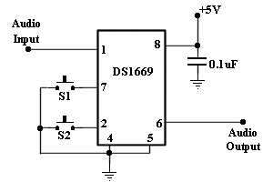
This circuit allows for amplifier volume control without the need for a potentiometer, utilizing an IC DS1669. The operating voltage for this type of IC ranges from 4.5 volts to 8 volts; however, in this circuit, it is used...
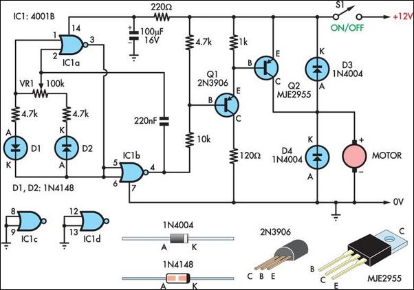
Two simple 12V DC motor speed controllers can be constructed for a minimal cost. These controllers take advantage of the principle that the rotational speed of a DC motor is directly proportional to the average value of its supply...
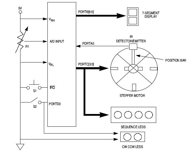
This article explains how to design a stepper motor system using an 8-bit Freescale microcontroller - MC68HC11E9. The design of a stepper motor system utilizing the 8-bit Freescale microcontroller MC68HC11E9 involves several key components and considerations to ensure effective control...

This circuit has been designed to alert the vehicle driver that he/she has reached the maximum fixed speed limit (i.e. in a motorway). It eliminates the necessity of looking at the tachometer and to be distracted from driving. There...
This circuit is designed for speed control of small DC motors commonly found in devices such as electric drills, which are utilized for precision engineering and drilling tasks. The behavior of these motors, typically permanent magnet types, resembles that...
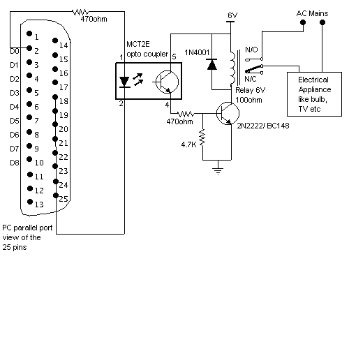
Here is a circuit for using the printer port of a PC for control application using software and some interface hardware. The interface circuit along with the given software can be used with the printer port of any PC...