
High Voltage Generation For Xenon Tube Applications

The NCP1532 is designed to facilitate efficient power management in applications requiring higher current output. When paralleling two NCP1532 converters, careful attention must be given to the design of the load-sharing circuit. The output voltage regulation of each converter is influenced by several factors, including the inherent tolerances of the bandgap reference and the offsets in the comparator circuits. These factors can lead to slight differences in output voltage between the two converters, necessitating the use of ballast resistors. These resistors help balance the load between the converters, ensuring that neither converter is overloaded and that both operate within their specified current limits.
To implement the load-sharing method effectively, the external resistor values must be calculated based on the expected load conditions and the tolerances of the converters. The goal is to select resistor values that are high enough to provide effective load sharing but low enough to minimize power losses. This balance is critical for maintaining the efficiency of the overall power system.
Additionally, the synchronization capability of the NCP1532 allows for improved electromagnetic interference (EMI) performance. By synchronizing the two converters to an external clock, designers can ensure that the switching noise is minimized, which is particularly important in sensitive applications. Operating the converters out of phase can also help to reduce input ripple current and improve overall system stability.
In summary, the NCP1532's dual-channel design, combined with careful consideration of external components and load-sharing techniques, enables the creation of efficient, compact power solutions for portable designs requiring higher current capabilities. Proper implementation of ballast resistors and synchronization techniques will enhance performance and reliability in demanding applications.Power demand in portable designs CAN require in some specific application more than 1 A. A method consists in paralleling two DC to DC converters on the same load instead of placing a single higher current converter with lower switching frequency. This solution may be space saving, cost effective and thermally beneficial. However, DC to DC convert ers regulate their own output voltage with a tolerance which includes bandgap deviation, Comparator offsets and closed loop regulation parameters. Using converters with external resistor bridge implies to also take into consideration resistor accuracies.
This application note will detail the tips and tricks to implement load sharing method with NCP1532. The NCP1532 dual step down DCDC converter includes two channels externally adjustable from 0. 9 V to 3. 3 V which CAN source totally up to 1. 6 A, 1. 0 A maximum per channel. The MODE/SYNC pin allows to force the part in PWM mode which is required to operate with the load sharing method. Both converter CAN operate out of phase at 2. 25 MHz or CAN be synchronized in phase to an external Clock External Components Must Be Evaluated Paralleling two DC to DC converters to increase output current capability requires additional ballast resistors to prevent the fact that the two converters are not exactly set at the same voltage.
Using the NCP1532 we CAN consider that the deviation coming from the error Amplifier and reference voltage CAN be negligee inside the same circuit. Handled designers must minimize these ballast resistors to reduce power looses and ensure acceptable load regulation performance.
🔗 External reference
Related Circuits
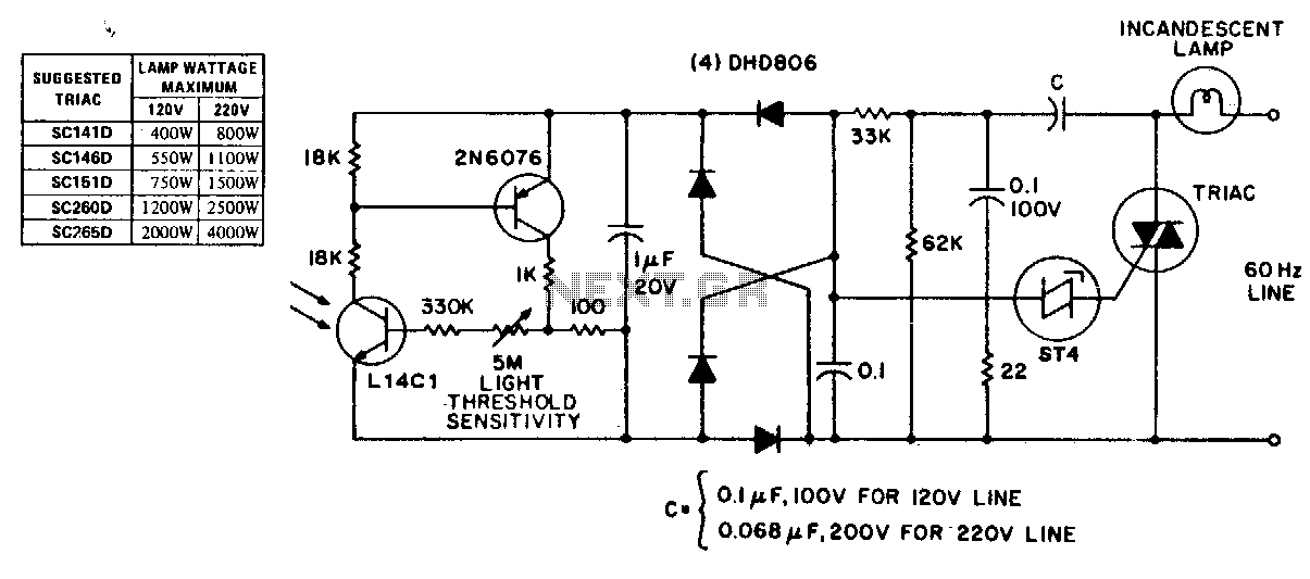
This circuit exhibits stable threshold characteristics based on the photo-diode current in the Ll4Cl, which generates a base-emitter voltage drop across the sensitivity setting resistor. The double phase shift network that supplies voltage to the ST-4 trigger ensures triac...

A high voltage power supply can be a beneficial source that can be utilized in various applications such as biasing gas-discharge tubes and radiation detectors. This power supply can also be employed for property protection through the electric charging...
This circuit comprises two identical intercom units. Each unit includes a power supply, a microphone preamplifier, an audio amplifier, and a Push To Talk (PTT) relay circuit. The units are interconnected using only two wires. Due to the low...
This is a high-power LED driver circuit designed to accommodate a wide input-voltage range. The circuit utilizes a buck/boost converter controller to regulate the current supplied to a white LED. The high-power LED driver circuit is engineered to effectively manage...
This article presents a high reliability 1200V High Voltage Integrated Circuit (1200V HVIC) for half bridge driver applications, aimed at reducing the IC's supply current by approximately 50%. The 1200V High Voltage Integrated Circuit (HVIC) is designed specifically for half-bridge...
If the offset value exceeds 5mV, adjust this value by experimenting with resistors, starting with 220K, connected from test point Z (the junction of R22 and R23) to +V if there is a negative voltage, or to -V if...