
Wide Input-Voltage Range High-Power LED Driver

The high-power LED driver circuit is engineered to effectively manage varying input voltages while ensuring optimal performance of the connected LED. The buck/boost converter configuration provides flexibility, allowing the circuit to step down or step up the input voltage as necessary to maintain a constant output current. This is critical for LED applications, as LEDs require a stable current for consistent brightness and longevity.
The circuit typically includes essential components such as an inductor, capacitors, diodes, and a feedback mechanism to monitor and adjust the output current. The inductor is responsible for storing energy during the switching cycle, while the capacitors smooth out the voltage and current to the LED. A Schottky diode is often used for its fast switching capabilities, which enhances the efficiency of the circuit.
The controller IC is central to the operation, providing pulse-width modulation (PWM) signals to control the switching devices (transistors or MOSFETs). By adjusting the duty cycle of these signals, the controller can finely tune the output current to the LED, compensating for variations in input voltage or load conditions.
Thermal management is also a significant consideration in high-power applications. Adequate heat sinking or thermal pads may be implemented to dissipate heat generated by the LED and the driver circuit, ensuring reliable operation under continuous load.
Overall, this high-power LED driver circuit is suitable for various applications, including automotive lighting, architectural illumination, and general-purpose lighting, where robust performance across a broad voltage range is required.This is a wide input-voltage range high-power LED driver circuit. This circuit based on a buck/boost converter controller regulates current to a white LED.. 🔗 External reference
Related Circuits
The following touch switch circuit utilizes a CA3240 dual BiMOS operational amplifier to detect small currents flowing between the contact points on a touch plate. The touch switch circuit employs a CA3240 dual BiMOS op-amp, which is known for...
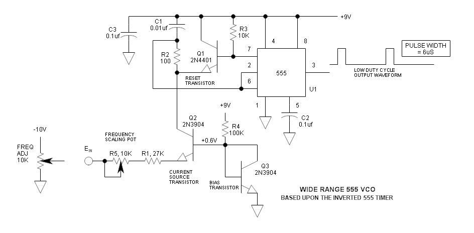
The frequency of the 555 timer can be adjusted by changing the voltage at pin 5. However, the range and linearity of this adjustment are quite limited. This can be significantly improved by using an inverted 555 timer circuit....
A phase-locked loop (PLL) is widely utilized in telecommunications, control systems, and various other electronic applications. PLLs can be employed to demodulate frequency-modulated (FM) signals and generate a stable output frequency. A phase-locked loop is an essential feedback control system...
Variable-gain amplifiers (VGAs) can be used in many types of systems, such as radio receivers. In this system, the input signal voltage depends on an. Variable-gain amplifiers (VGAs) are integral components in various electronic systems, particularly in radio receivers where...
An LED, or Light Emitting Diode, is a semiconductor device that allows current to flow in one direction while blocking it in the opposite direction. This characteristic makes LEDs polarized components, having a positive side known as the anode...
This circuit, designed on request, has proven to be useful to indicate when the voltage in a power supply line is changing from 120V to 240Vac. It can be used in different circumstances and circuits, mainly when an increase...