
High voltage generator circuit

The circuit design encompasses three critical components: the oscillator, the switching stage, and the step-up transformer. The oscillator, based on the NE555 timer, generates a square wave signal at a frequency of 25 kHz. This frequency is essential for the subsequent stages of the circuit, as it determines the operating frequency of the entire system.
The NE555 timer is configured in astable mode, producing a continuous output signal that toggles between high and low states. This output is connected to the base of the TIP3055 power transistor, which serves as a switch. The TIP3055 is a high-power NPN transistor capable of handling significant current, making it suitable for this application. When the NE555 timer outputs a high signal, the TIP3055 is turned on, allowing current to flow through the primary winding of the step-up transformer.
The step-up transformer plays a vital role in this circuit by increasing the voltage from the primary side to the secondary side. The transformer is designed to operate at the same frequency as the oscillator, ensuring efficient energy transfer. As current flows through the primary winding, a magnetic field is established, which induces a high voltage in the secondary winding due to the transformer's turns ratio.
Safety precautions must be emphasized when working with this circuit. Proper insulation, protective equipment, and adherence to safety protocols are essential to prevent electric shock or other hazards. This circuit should only be constructed and tested in a controlled environment by individuals with adequate knowledge of high-voltage systems.First of all let me remind you that this circuit is a very dangerous one. The output voltage of this circuit is in Kilo volts and it can seriously injure you or kill you. Try this circuit only if you have enough experience dealing with high voltages. I have no responsibility on any hazards caused by the circuit. Be very careful. This is a humble r equest. The circuit given here has three sections namely oscillator, switching stage and a step up stage. The oscillator is build around a NE555 timer operating at 25 KHz. The output of the NE555 coupled to the base of the power transistor TIP3055 which is the switching device. The power transistor drives primary of the step up transformer at 25 KHz and as a result a high voltage will be induced across its secondary.
🔗 External reference
Related Circuits
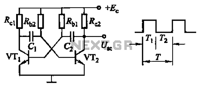
Common non-sinusoidal oscillator circuit, waveform and frequency formula - square wave oscillator - self-excited multivibrator The common non-sinusoidal oscillator circuit, specifically the square wave oscillator, is a fundamental electronic circuit utilized to generate square wave signals. It operates based on...
An LED, or Light Emitting Diode, is a semiconductor device that allows current to flow in one direction while blocking it in the opposite direction. This characteristic makes LEDs polarized components, having a positive side known as the anode...
This circuit generates audio musical notes that can be heard from a distance of up to 10 meters. It consists of two main components: an infrared (IR) music transmitter and an IR music receiver. The IR music transmitter operates...
This circuit is a simple series tone control circuit utilizing the OP-Amp LM301A. The JFET 2N3684 provides high input impedance and low noise characteristics for the feedback buffer in the op-amp-based tone control. The tone control circuit described employs an...
The following circuit illustrates the connection of the Devantech SRF04 Ultrasonic Sensor to the SV203 powered PPRK Circuit Diagram. This circuit is based on the Devantech SRF04 sensor and features a minimum initiation time of 10 milliseconds for the...
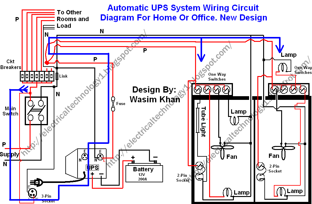
This wiring circuit diagram is designed for providing power to specific rooms in a home or office during a power supply failure. It ensures continuous power supply to devices such as laptops and computers in those particular rooms, especially...