
High voltage generator excitation set overvoltage protection circuit
The described circuit employs a three-phase thyristor rectifier to convert AC voltage into DC voltage for the generator's field winding. This conversion is critical for maintaining the operational integrity of the generator, as it ensures that the excitation system receives the necessary voltage to function effectively. However, the reliance on thyristors introduces potential risks, particularly during abnormal operating conditions such as phase imbalances or system failures.
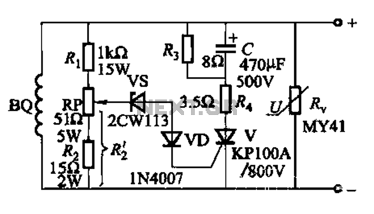
In response to these risks, the protection circuit, as depicted in Fig. 13-90, incorporates a varistor, which is a voltage-dependent resistor designed to clamp excessive voltage levels. The varistor operates by transitioning from a high-resistance state to a low-resistance state when the voltage exceeds a predetermined threshold, thereby diverting excess energy away from sensitive components in the circuit. This action prevents damage to the field winding insulation, which could otherwise lead to catastrophic failures.
The excitation windings, represented by BQ in the schematic, are crucial for generating the magnetic field necessary for the generator's operation. The design of the protection circuit ensures that these windings remain operational under varying conditions, thereby enhancing the reliability and longevity of the generator system.
Overall, the integration of a three-phase thyristor rectifier with an effective over-voltage protection scheme is essential for the safe and efficient operation of DC-powered generator systems. The use of components such as varistors plays a pivotal role in safeguarding against voltage surges, ensuring continuous performance and preventing costly downtimes.DC voltage of the generator field winding by a three-phase thyristor rectifier provided later. In the same period incorrect, out of step, system failure, etc., the rectifier wi ll cause hazardous elements and the field winding on the DC side over-voltage insulation, this must limit over-voltage, commonly used as shown in Fig. 13-90 protection circuit. Figure, BQ as excitation windings. Varistor R, as a back-up over-voltage protection element.
Related Circuits
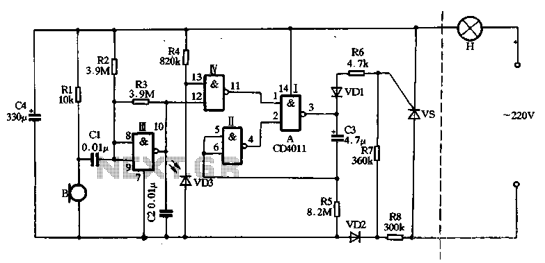
The main circuit utilizes a two-input NAND gate composed of four digital integrated circuits. This includes a NAND gate microphone amplifier circuit, a light control mechanism using an "AND gate," and a monostable delay control circuit formed by NAND...
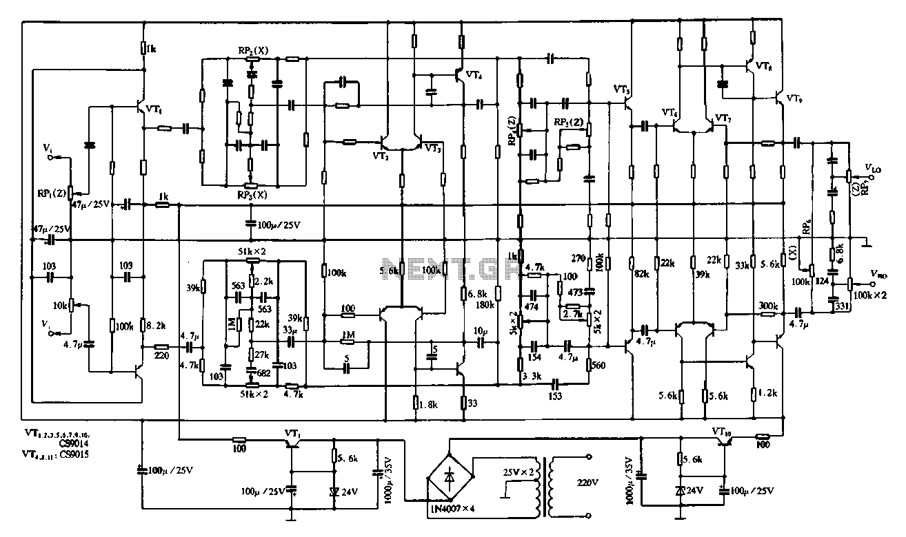
Figure 4-11 illustrates a feedback attenuator that comprises a transistor-based tone control circuit. This circuit features a conventional high and bass control system, along with balance control, volume control, loudness adjustment, and subwoofer control, as well as field sense...
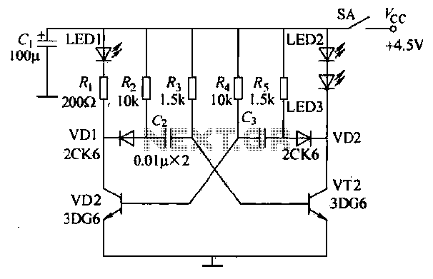
The infrared transmitter circuit, as depicted in Figure 18-la, utilizes transistors VT1 and VT2 along with RC components to create an astable multivibrator. The circuit operates with VT1 and VT2 receiving base bias from resistors, and closing switch SA...
The controller for the Hybrid Power Plant (HPP) is represented in a block diagram format. It consists of 440 Wp photovoltaic modules, a 1 kW wind turbine, and a 5 kW diesel engine as a backup power source. The...
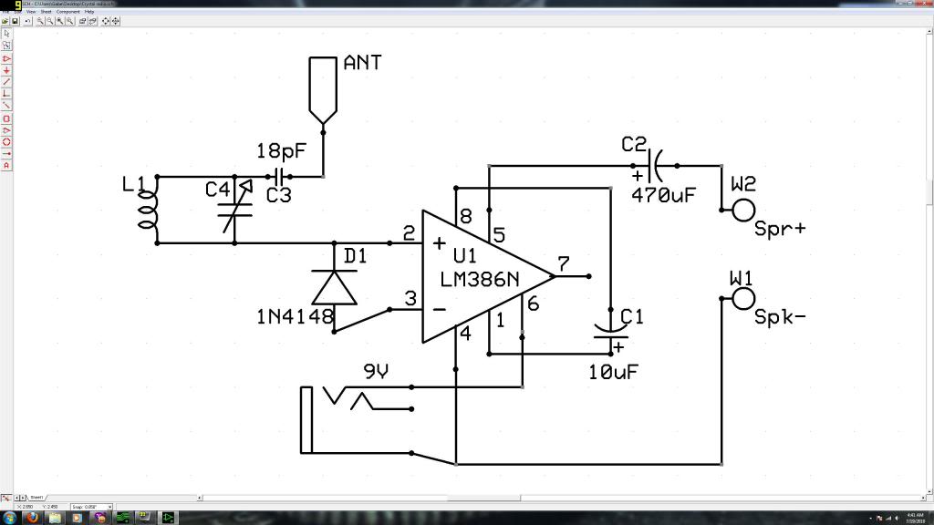
Initially, the individual has limited experience in electronics. They constructed a crystal radio circuit using components salvaged from a non-functional radio, including an LM386N audio amplifier. A crystal radio circuit is a simple radio receiver that operates without the need...
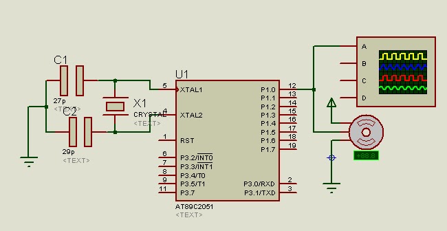
A program is available to control a simple servo motor in both directions. This program has been tested and can be shared for others to benefit from it. It allows the servo motor to rotate in both clockwise and...