
Transistor attenuation - feedback tone circuit

The feedback attenuator circuit detailed in Figure 4-11 serves as a sophisticated audio processing tool, integrating various control mechanisms to enhance sound quality and user experience. The use of a 24V power supply is critical, as it allows for higher headroom and reduced distortion across the audio spectrum. The differential amplifier configuration is essential for maintaining a high signal-to-noise ratio, which is crucial for high-fidelity audio applications.
The interaction between the volume control potentiometer and the loudness control potentiometer (P7) is particularly noteworthy. This design allows for a seamless adjustment of loudness without introducing significant distortion, thus preserving the integrity of the audio signal. The attenuation process through RPi and the subsequent impedance transformation via VTi ensures that the signal maintains its quality as it passes through the tone control circuitry.
The telepresence control (RP2) offers versatility in sound shaping, enabling users to adjust the presence of mid-range frequencies, which can significantly affect the perceived clarity and detail of the audio. The subwoofer control (RP3) is designed to manage low-frequency output effectively, ensuring that bass response is both impactful and controlled, particularly during dynamic musical passages.
In addition, the bass control potentiometer (RP4) and treble control potentiometer (RPs) provide further customization options, allowing users to tailor the audio output to their preferences. This comprehensive control scheme enables a high level of audio fidelity and personalization, making the feedback attenuator circuit an invaluable component in advanced audio systems. Overall, the circuit exemplifies a well-engineered approach to audio processing, balancing complexity with user-friendly controls for optimal sound reproduction.Figure 4-11 is a feedback attenuator consisting of transistors tone control circuit. The circuit in addition to a conventional high, bass control system, balance control, volum e control loudness, but also with subwoofer control, field sense of control. In order to improve the transient characteristics of the entire tonal system and reduce distortion, this circuit uses a high operating voltage, 24V supply voltage. In the circuit node configuration using the excellent performance of the differential amplifier circuit as a signal to noise ratio of the circuit, the dynamic range to achieve a higher level of technology.
In the circuit, coral, volume control potentiometer is pre-din, and its subsequent stage loudness volume control potentiometer P7 brush with each other, can obtain better compensation effect of loudness while enhancing the ability to overdrive the input stage and improve playback signal to noise ratio. After the signal from the input stage by RPi attenuation through the emitter VTi constituted after the output impedance transformation, namely into the NF type tone circuitry for processing o foot) 2 as telepresence control potentiometer capable of 500 ~ 2000Hz frequency signal within the boost or attenuation around 6 f8dB, can be used to control the system and the atmosphere, increased presence.
RP3 control potentiometer for the subwoofer, it is generally the bass controller is different in frequency from the control to its lower turning point made about 100Hz. So when playing a larger dynamic music, the bass and soft but with a touch. After the feedback tone control circuit is changed after a group of straight bass High attenuation control circuit.
RP4 bass control potentiometer, it subwoofer control potentiometer RP3 can better control with low frequency interest, especially in the low frequency response of. RPs for the treble control potentiometer. The proper use of the controller, can effectively improve the clarity of the program.
Related Circuits
Simple FM Transmitter Circuit This simple FM transmitter circuit was built using a transistor with a transmission distance of about 300m around your home. The simple FM transmitter circuit utilizes a transistor to modulate audio signals onto a radio frequency...
The LM1036 is a DC-controlled circuit designed for managing tone (bass and treble), volume, and balance functions in stereo applications, including car radios, televisions, and audio systems. Component: . The LM1036 integrates multiple audio control functionalities into a single chip,...
This page presents a replacement circuit for the LM3909 LED Flasher/Oscillator utilizing discrete components. The circuit functions similarly to the integrated LM3909 but features minor variations in the component values used. Although the LM3909 is still available, it tends...
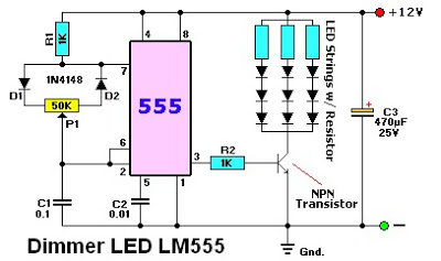
The LM555 timer IC can be utilized in various electronic projects, including the creation of an analog timer. According to the datasheet, the LM555 is versatile and can be adjusted to set timers based on specific requirements. The schematic...
This design circuit project involves a clear glass sensor circuit intended for experimental or hobbyist applications. The concept is straightforward and relies on a homemade sensor unit that includes one high-efficiency ultra-bright red LED (D1) and a standard phototransistor. The...
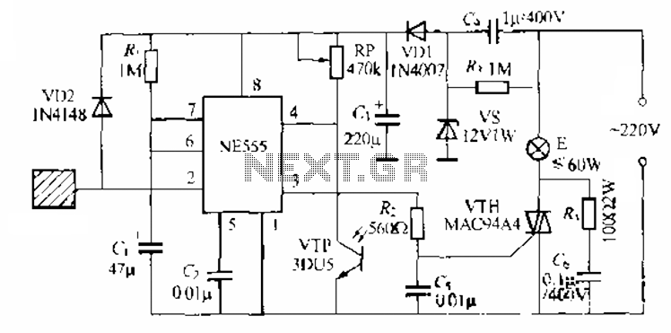
The circuit utilizes a NE553 automatic light sensor composed of 55 groups, allowing lights to turn on when individuals are present and turn off when they leave. The power supply includes VD1, vS, and C, with a 12V DC...