
High voltage power supply

The circuit design for the switch-mode power supply (SMPS) based on the TL494 integrated circuit is a versatile and efficient solution for powering nixie tubes. The TL494 is a popular choice for power supply applications due to its built-in features, such as a voltage error amplifier and pulse-width modulation control, which allow for precise regulation of output voltage.
The adjustable output voltage is facilitated by a potentiometer connected to the feedback loop of the TL494. This enables fine-tuning of the voltage supplied to the nixie tubes, ensuring optimal performance and longevity. The specific voltage range (XX to YY) should be empirically determined to match the requirements of the nixie tubes in use.
In terms of component selection, the original design utilized a 250V output capacitor, which proved inadequate in certain scenarios, leading to component failure. To mitigate this risk, the use of a 450V output capacitor is strongly recommended. This higher voltage rating provides a safety margin, accommodating potential voltage spikes and ensuring reliable operation over time.
The power supply circuit typically includes other essential components such as inductors, diodes, and filtering capacitors, which help to stabilize the output and reduce ripple voltage. The choice of these components should be made carefully, considering their voltage and current ratings to match the expected load.
Overall, this switch-mode power supply design is an effective solution for nixie tube applications, providing the necessary voltage and current while ensuring safety and reliability through thoughtful component selection and circuit design.The design is based on the TubeHobby and is the power supply used in their NC2. I built this very kit as my first nixie tube project, and you can find a review of this excellent kit in the reviews section of my blog. The circuit is a switch-mode power supply based on the popular TL494. I recommend grabbing a dozen or more of these chips from your favorite supplier, as it`s also the chip used in my plasma speaker projects.
The voltage is controlled by the potentiometer, allowing a range of XX to YY (todo: measure this) with the default components. The original design used a 250V output capacitor, but after burning one of those out with a carelessly high voltage setting, I think it`s wise to have the extra leeway afforded by a 450V cap if you have one.
🔗 External reference
Related Circuits
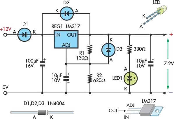
This circuit allows an external 12V SLA battery to power a camcorder that typically uses a built-in 7.2V battery. Obtaining such batteries for older camcorder models can be challenging and costly. The circuit utilizes a standard LM317 adjustable voltage...
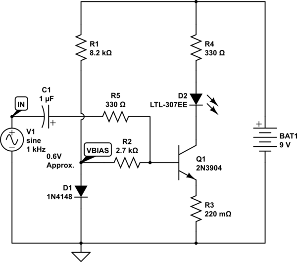
The goal is to take the voltage output from a 3.5mm audio jack and use it to light up an LED based on the audio voltage levels. The left audio channel will be connected to the base of a...
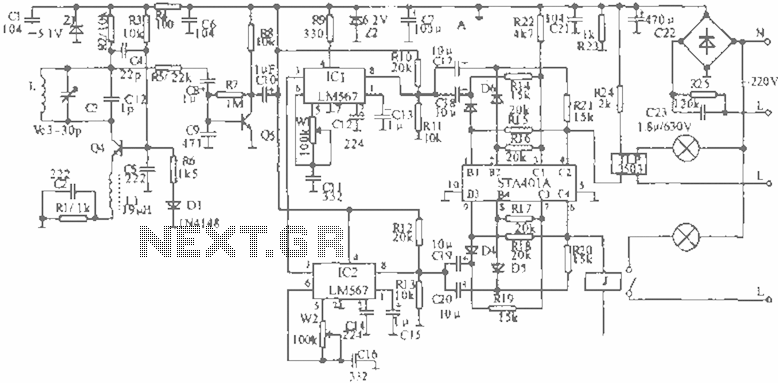
When the infrared receiver tube PH302 receives a signal from the remote control, the CX20106A selected frequency amplifier outputs a low-frequency signal. The low-level signal charges capacitor C through diodes D and R, causing the negative side potential of...
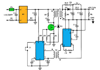
The schematic above illustrates a 10A power supply with a 5V output and a power rating of 50W. It operates as a flyback converter in continuous mode. The circuit includes both primary and secondary side controllers, providing comprehensive protection...
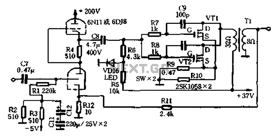
The amplifier circuit illustrated in Figure 2-25 features the following: (1) It utilizes a class 6N11 tube for parallel push-pull amplification, providing high-frequency response and an excellent signal-to-noise ratio. (2) The final stage of the semiconductor amplifier does not...
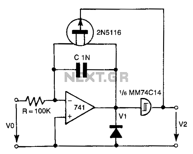
The 741 operational amplifier integrator signal is input into the Schmitt trigger of an inverter. When the signal reaches the positive-going threshold voltage, the inverter's output switches to zero. This output directly controls the FET switch. With a gate...