
Homemade TV remote control off electrical power supply circuit

The circuit operates based on an infrared remote control system, utilizing the PH302 infrared receiver to detect signals emitted from the remote. Upon receiving a signal, the CX20106A amplifier processes the input, amplifying the low-frequency signal to a level suitable for further processing. The output from the amplifier is directed to a capacitor, denoted as C, which plays a crucial role in the timing and control of the relay mechanism.
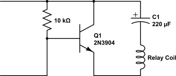
Diodes D and R are integral components that facilitate the charging of capacitor C. As the capacitor charges, the voltage across its terminals rises until it reaches a threshold of 1/3 Vcc. This threshold is significant as it is the point at which the 555 timer, configured in monostable mode, triggers a discharge cycle. The discharge effectively activates the relay, which is responsible for controlling the power supply to a connected load.
The relay operates under a self-locking mechanism once switch S1 is engaged. This means that once the relay is activated, it remains in the on state until power is removed, allowing for continuous operation without the need for constant input from the remote control. The sensitivity of the RC circuit can be fine-tuned to adjust the response time of the system, typically set within a range of 3-5 seconds for optimal performance. This ensures that the system can reliably respond to user commands while preventing accidental activation.
Overall, this circuit design exemplifies a practical application of infrared communication and relay control, suitable for various electronic projects requiring remote operation and automated power management.When the infrared receiver tube PH302 receives a signal from the remote control, the CX20106A selected frequency amplifier output a low-frequency signal, the low-level signal by the D and R charges C, so C negative side potential falls below 1 / 3Vcc , .png">555 circuit discharge cutoff relay shock release, cut off the power supply. RC circuit sensitivity can be set to the action, press the remote control is generally 3-5 seconds. Press S1 relay circuit namely self-locking when powered on.
Related Circuits
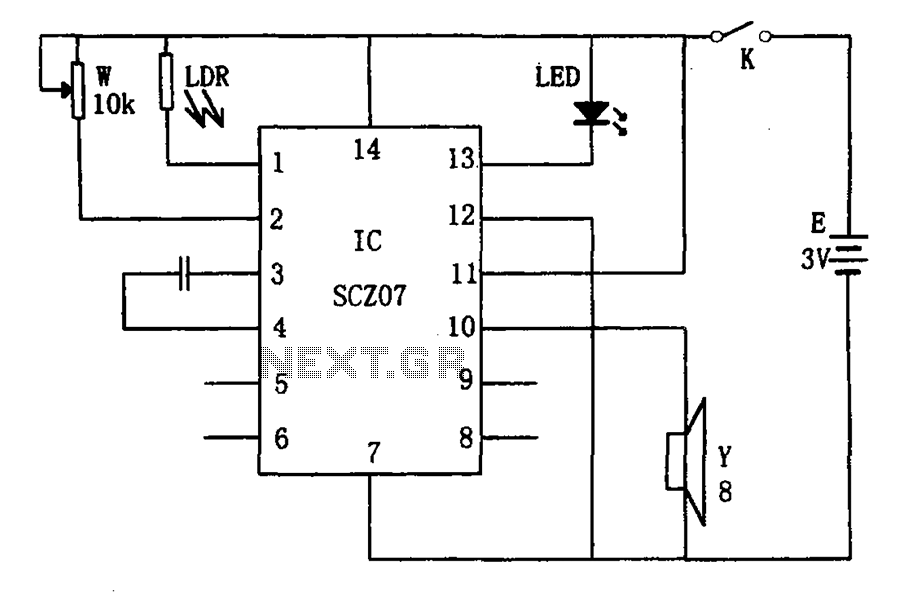
The weak light alarm circuit is illustrated in the figure. The oscillator circuit's core component is the SCZ07. The input signal is controlled by a potentiometer (W) and the output signal is processed by a photoresistor (LDR). The circuit...
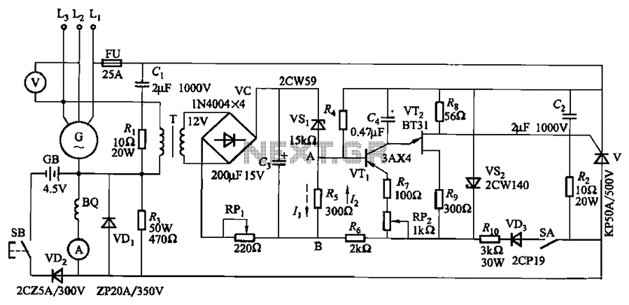
The circuit depicted in Figure 7-32 is designed for an excitation device capable of handling a terminal voltage of 400V and a capacity of less than 75kW for synchronous generator motors, enabling automatic adjustment of excitation. When the generator...

The TDA6106Q test circuit, as depicted in the provided figure, operates with a feedback factor of 1/116. The input signal, Vin, is received from the input network consisting of resistors R1, R9 and capacitors C1, C2. The TDA6106Q IC...
A single-coil latching relay is utilized, which can latch and reset with opposite polarities. Testing of the circuit with dual opposite-biased LEDs showed no flickering in either direction, indicating stable charge and discharge behavior. However, there are concerns regarding...
The purpose of this circuit is to animate shop windows using a capacitive sensor positioned behind a postcard-like banner. The card is placed against the glass inside the shop window, allowing visitors to activate the relay by placing their...
To achieve optimal audio reproduction at various listening levels, it is essential to incorporate tone-setting controls that align with the well-documented characteristics of human auditory perception. Specifically, human ear sensitivity exhibits a non-linear response across the audible frequency spectrum,...