
5v 10a output switching power supply

The described power supply circuit is a flyback converter designed to deliver a stable 5V output with a maximum current of 10A, achieving a total power output of 50W. The flyback topology is particularly suited for applications requiring electrical isolation and voltage step-down capabilities. The continuous mode operation ensures that the energy transfer from the primary to the secondary winding occurs consistently, resulting in improved efficiency and reduced electromagnetic interference (EMI).
The primary side controller regulates the input voltage and manages the switching operation of the power transistor, typically a MOSFET, which controls the energy transfer to the transformer. The transformer in a flyback converter serves a dual purpose: it provides isolation between the input and output, and it stores energy during the on-time of the switch. The secondary side controller monitors the output voltage and current, ensuring that the output remains stable under varying load conditions.
Protection features are integral to the design of this power supply. The overcurrent protection mechanism prevents excessive current flow that could damage the circuit components. In the event of a fault condition, the circuit is designed to shut down or limit the output until the fault is cleared. After rectifying the fault, the soft start feature gradually ramps up the output voltage, minimizing inrush current and preventing stress on the components.
Overall, this power supply design exemplifies robust engineering principles, combining efficiency, safety, and reliability for various electronic applications.The Schematic above shows a 10A power suplly with a 5V output and with power 50W. It is a flyback converter operating in the continuous mode. The circuit features a primary side and secondary side controller with full protection from fault conditions such as overcurrent. After the fault condition has been removed the power supply will enter the so ft start cycle before recomming normal operation. 🔗 External reference
Related Circuits

The following circuit is an example of how to get power from an RS-232 serial port. It provides regulated +5V power for logic circuits and also unregulated positive and negative power supplies for the RS-232 transmitting circuit. The circuit...
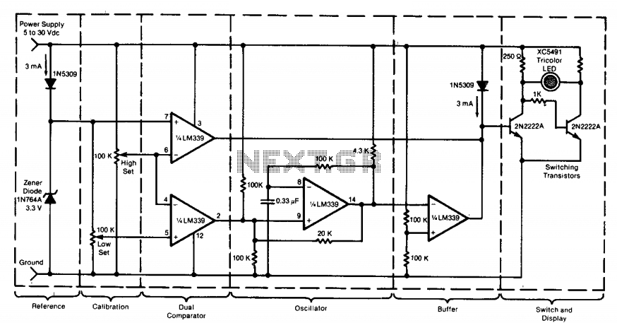
This circuit utilizes a tricolor LED display to signify acceptable and unacceptable output voltages. One LED indicates the upper voltage limit, while another indicates the lower voltage limit. When the monitored voltage exceeds the maximum set point, the LED...
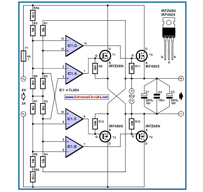
The losses in a bridge rectifier can easily become significant when low voltages are being rectified. The voltage drop across the bridge is approximately 1.5 V. In a bridge rectifier circuit, the configuration consists of four diodes arranged in a...

The circuit depicted features a secondary N3 center tap transformer (T) with a common point connecting diodes VD2 and VD3 to positive electrodes, along with capacitors C2, C6, C7, and negative electrodes connected to capacitors C9 and C10. Additional...

A decrease in the resistance of the CDS cell when light strikes it activates latch A and B, enabling tone oscillator C and D, which produces an output of about 1000 Hz. RA sets the trip level. SI resets...
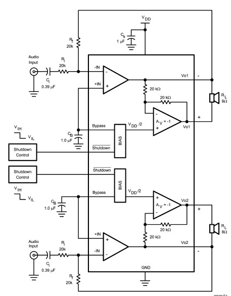
The LM4992 stereo audio power amplifier can be utilized to design a straightforward audio power amplifier project suitable for portable electronic devices. This amplifier circuit is capable of delivering 1 watt of continuous average power per channel to an...