
high voltage power supply circuit for fluorescent light

The high-voltage power supply circuit designed for fluorescent lights typically consists of several key components that work together to convert standard low voltage AC into the high voltage AC required to ignite and sustain the fluorescent lamp. The circuit usually includes a transformer, a rectifier, a capacitor, and a ballast.
1. **Transformer**: The transformer steps up the low voltage AC input (usually 120V or 240V) to a much higher voltage, often in the range of 1000V to 3000V. This high voltage is essential for starting the fluorescent lamp. The transformer is designed with a suitable turns ratio to achieve the required output voltage.
2. **Rectifier**: After the transformer, a rectifier is employed to convert the high voltage AC into high voltage DC. This can be accomplished using diodes arranged in a bridge configuration. The rectification process is crucial for ensuring that the voltage delivered to the lamp is unidirectional, which is necessary for stable operation.
3. **Capacitor**: A capacitor is often included in the circuit to smooth out any ripples in the DC output from the rectifier. This ensures that the voltage supplied to the fluorescent lamp is consistent and reduces flickering, which can occur if the voltage fluctuates.
4. **Ballast**: The ballast is a critical component that regulates the current flowing through the fluorescent lamp. It provides the necessary starting voltage to initiate the lamp and limits the current during normal operation to prevent damage. The ballast can be either electromagnetic or electronic, with electronic ballasts providing better energy efficiency and performance.
5. **Safety Features**: Due to the high voltages involved, safety features such as fuses, circuit breakers, and protective enclosures are often included to prevent electrical hazards. These components help to ensure that the circuit operates safely under various conditions.
In summary, the high-voltage power supply circuit for fluorescent lights integrates a transformer, rectifier, capacitor, and ballast, along with necessary safety features, to effectively power fluorescent lighting systems. Proper design and implementation of these components are essential for reliable and efficient operation.High-voltage power supply circuit for fluorescent light power supply. Go to that page to read the explanation about above power supply related circuit diagram. 🔗 External reference
Related Circuits
Many battery-powered devices use two AA alkaline cells. Often, it is not apparent when it is time to replace the batteries until the device powered by them ceases to function. In battery-powered devices that utilize two AA alkaline cells, it...
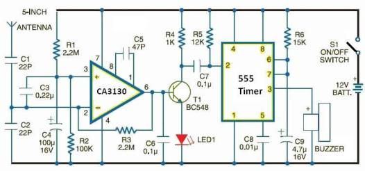
This electronic schematic can be used to design a simple cellular phone detector circuit capable of sensing the presence of an activated mobile phone from a distance of approximately 1.5 meters. The C3 capacitor should have lead lengths of...
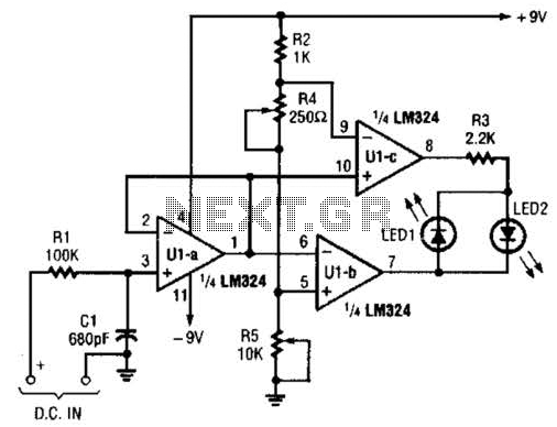
Transistors Q1 and Q2, along with resistors R1 through R7, form the input balancing stage that measures the resistance between points X and Y. This stage operates as a bridge circuit, incorporating resistors R1, R2, R6, R7, and the...
The following circuit illustrates a Video and DVD Modulator in a VHF/UHF electronic diagram. Features include an oscillator that utilizes a transistor for high-frequency operation. The video and DVD modulator circuit serves to convert video signals into a format suitable...
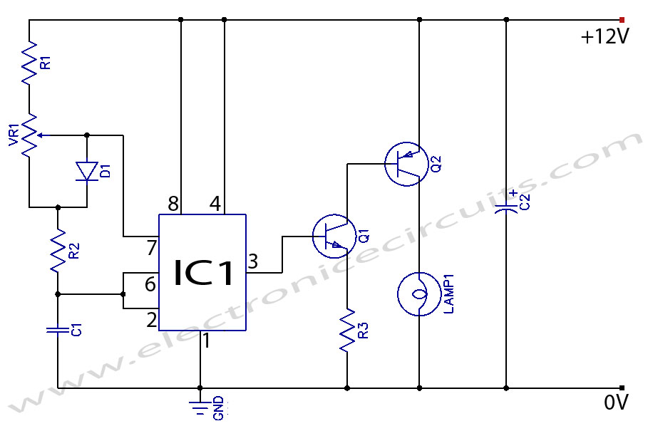
When the potentiometer is in the upper position, the capacitor charges rapidly through both 1k resistors and the diode, resulting in a brief positive interval and an extended negative interval, which dims the lamp to near darkness. Conversely, when...
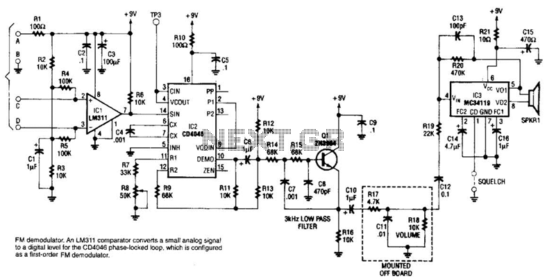
An LM311 comparator converts a small analog signal to a digital level for the DC4046 phase-locked loop, which is configured as a first-order FM demodulator. This demodulator operates with a 50-kHz FM modulated input signal and has applications in...