
High Voltage Power Supply for Geiger Tubes

These power supply circuits are designed to generate high voltages, with a standard output of 500 volts that can be adjusted to range from a few hundred volts to nearly 1000 volts through the modification of zener diodes. The circuits are constructed to ensure safety and efficiency, with an emphasis on the qualifications of the builder, given the potential hazards associated with high voltage systems.
The operation of the circuit is based on feedback control, where the feedback signal increases the base voltage of the 2N4403 transistor to halt the oscillator instead of drawing current from the emitter's capacitor. This design choice reduces power dissipation significantly when the load is minimal or nonexistent. The circuit demonstrates a low current draw of less than 0.5 mA when powered at 9 volts without a load, utilizing a 1:1 audio isolation transformer with a 600-ohm rating.
For modifications, the circuit can be adapted to work at lower voltages by using a high-gain transistor, such as the MPSA18. The use of 120-volt zener diodes is recommended over standard diodes, as the latter often require grading, which can complicate the design. The 1N5273A is suggested as a suitable zener diode for this application.
The circuit's output is limited to a few microamperes, which poses a challenge when measuring with a standard 10-megohm voltmeter, as this load can significantly affect the output voltage. To mitigate this, the inclusion of a 10-megohm resistor in series with the diodes is beneficial, allowing for more accurate measurements and reducing the risk of damage during testing. The circuit's design ensures that under normal conditions, the current should remain below 0.5 mA with no load present.
Incorporating gas discharge devices, like neon bulbs, in place of zeners is also viable, facilitated by the series 10-megohm resistor. Additionally, a 1 µF capacitor can be added between the base and emitter of the MPSA18 to enhance circuit performance. This modification has been shown to allow a Lumex gas discharge tube to effectively regulate the output voltage at 600 volts while consuming only 300 µA in an unloaded state.
The prototype utilizes a small isolation transformer, with the primary and secondary windings connected in a manner that boosts the output voltage. Alternative transformer types, including compact audio interstage transformers, can be employed provided they maintain high impedance on both sides. Should the expected high voltage not be achieved, reversing one of the transformer winding connections may resolve the issue. In cases where the current does not decrease under no load, the previously mentioned techniques should be revisited. The circuit can also operate without the secondary connection, allowing for a direct connection from the collector of the MPSA42 to the first 0.02 µF capacitor and diode, with the secondary winding left unconnected. Employing the two-winding voltage boost is particularly advantageous when attempting to run the circuit on lower supply voltages.These power supply circuits are generating 500 volts but they may be modified to supply a couple of hundred to nearly 1000 volts by changing the zener diodes. These circuits generate high voltages and can cause dangerous shocks! Do not build these devices unless you are experienced and qualified to work on high voltage devices The difference is su
btle; the feedback signal increases the voltage on the base of the 2N4403 to stop the oscillator instead of stealing current from the capacitor on the emitter. The result is much lower power dissipation when there is little or no load on the high voltage. The new circuit draws less than 1/2 mA when operating at 9 volts without a load using a 1:1 600 ohm audio isolation transformer.
The 3 volt circuit may be modified in the same way but make sure to switch to a MPSA18 (or a similar very high gain transistor). The 120 volt zeners are also an improvement over trying to grade ordinary diodes; grading is just too much trouble!
A 1N5273A is a typical type to try. Remember, this circuit can only supply a few microamperes so an ordinary 10 megohm voltmeter will load the output too much. (500 volts/10 megohms = 50 uA. ) With some transformers and zeners, the circuit will work better if the 10 megohm resistor is moved up to be in series with the diodes (see next schematic).
It is a good idea to add a resistor in series with the diodes anyway, perhaps 100 k, to prevent damage when probing around. When operating properly, the current should drop down to below 1/2 mA with no load. The series 10 megohm resistor will make gas discharge devices work well in place of the zeners, too (neon bulbs, for example).
Also try a. 1 uF capacitor from base to emitter of the MPSA18. This capacitor modification combined with the series 10 megohm allowed a single Lumex gas discharge tube to regulate the output voltage of the circuit at 600 volts while drawing only 300 uA, unloaded. The transformer in the prototype is a small isolation transformer with opposite ends of the primary and secondary connected together to boost the output voltage.
Other transformers will also work, including tiny audio interstage transformers, as long as the impedance is relatively high on both windings. If you don`t get a high voltage, try reversing one of the winding connections. If the current doesn`t cut back with no load, try the techniques mentioned in the note above. The circuit will work without the secondary connection simply by connecting the collector of the MPSA42 directly to the first.
02 uF cap. and diode and leaving the secondary winding disconnected. Using the two winding voltage boost is recommended when attempting to run the circuit on a lower supply voltage. 🔗 External reference
Related Circuits
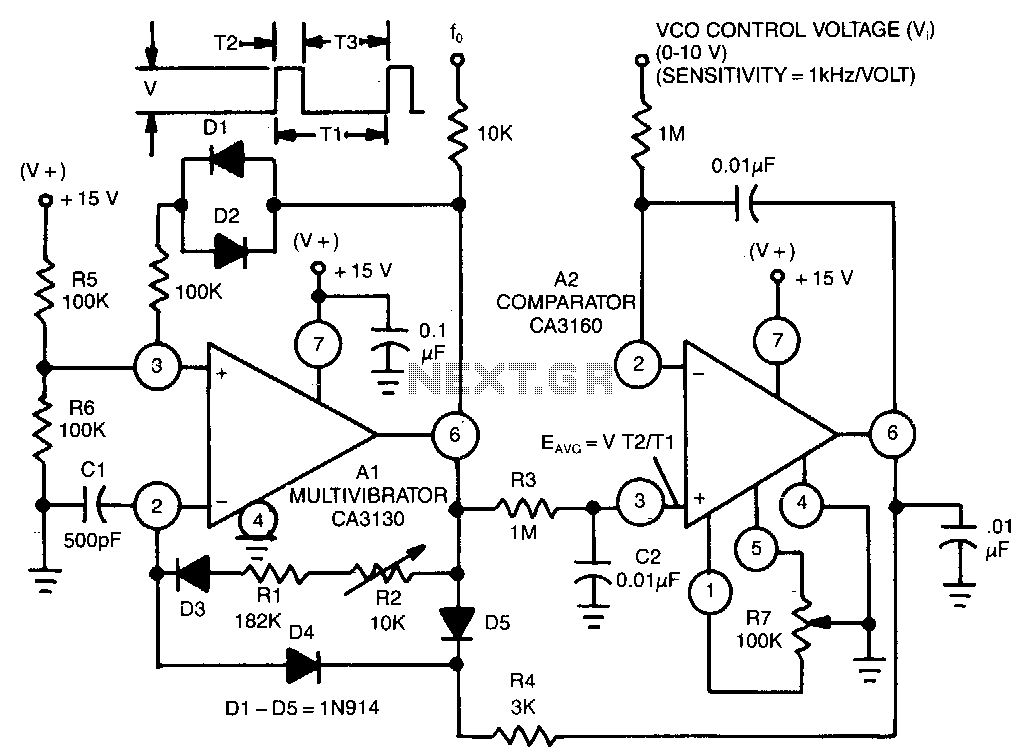
This circuit utilizes a CA3130 BiMOS operational amplifier as a multivibrator and a CA3160 BiMOS operational amplifier as a comparator. The oscillator exhibits a sensitivity of 1 kHz/V, with a tracking error of approximately 0.02% and a temperature coefficient...
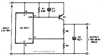
The IC8211 serves as a voltage reference and regulator amplifier, with Q1 likely functioning as the series pass transistor. R1 determines the output current of the IC8211, while C1 and C2 contribute to loop stability and help suppress the...
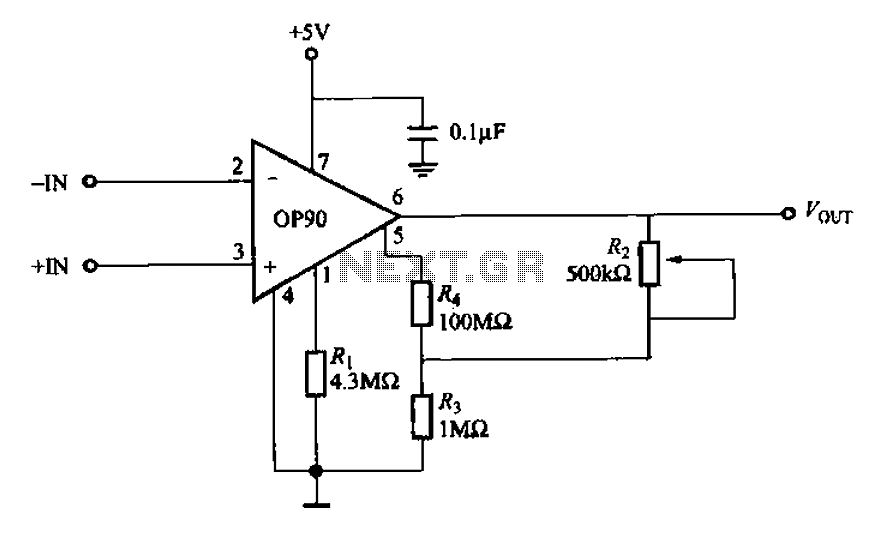
Compared to other operational amplifiers, the OP90 has a significant advantage in low power consumption. Its low power requirements allow for a wide range of power supply voltages (from 1.6V to 18V, and it can also operate with dual...
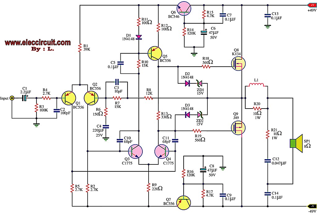
This is the first MOSFET power amplifier designed, featuring a comprehensive circuit. As a 60-watt power amplifier, it is adequate for typical usage. The 60-watt MOSFET power amplifier circuit is designed to deliver high efficiency and robust performance for audio...
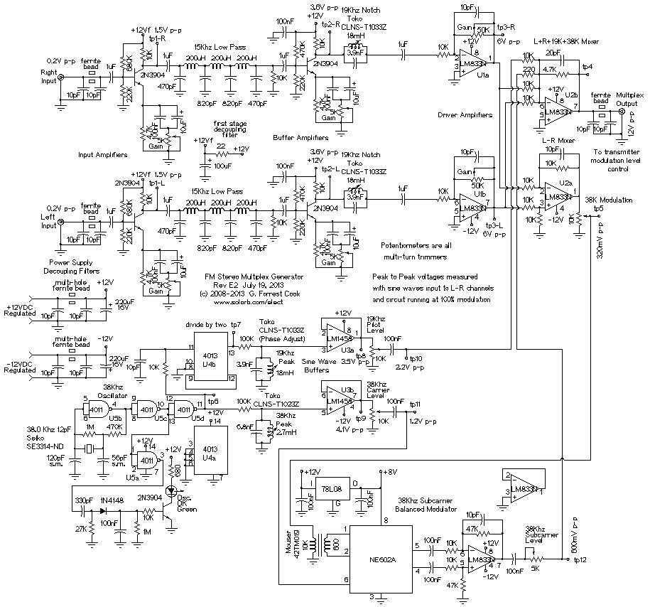
Here are some utility circuits for use with the Ramsey FM10a, and other small FM stereo transmitter kits. This information may be helpful for setting up a micro powered FM radio station. The FM10a and similar kits tend to...
The foundation of an audio mixer is an inverting summing circuit. In practical audio mixers, a single-supply voltage is rarely utilized. To enhance dynamic range, ... The inverting summing circuit serves as a fundamental building block in audio mixing applications,...