
Highly Stable 60Hz Sine-Wave Source Circuit

This circuit is designed to generate a highly stable 60-Hz sine wave output, which is often required in various applications such as signal processing, timing circuits, and audio systems. The stability of the sine wave is primarily achieved through the use of a specific configuration that simplifies the amplitude control mechanism compared to traditional methods.
The core of the circuit typically includes an oscillator or a waveform generator that produces the desired frequency. This oscillator can be based on a variety of components, including operational amplifiers, transistors, or dedicated waveform generator ICs. The output from this stage is then processed to ensure a clean sine wave with minimal distortion.
To maintain the amplitude stability of the sine wave, the circuit employs a feedback mechanism that continuously monitors the output. This feedback loop adjusts the gain of the oscillator to compensate for any variations in supply voltage or load conditions, ensuring that the output remains consistent.
The role of capacitor coupling in the final stage is critical. By using capacitors to couple the output, any DC offset introduced by the circuit components—such as unequal Zener voltages in the clipping circuit—is effectively removed. This allows for a pure AC sine wave to be delivered without any unwanted DC components that could interfere with downstream applications.
The clipping circuit, which follows the comparator, is responsible for limiting the output amplitude to prevent distortion. It typically employs Zener diodes that clamp the voltage to specific levels. However, variations in the Zener characteristics can introduce DC offsets. The capacitor coupling mitigates this issue by blocking DC while allowing the AC signal to pass through, ensuring that the output is a clean sine wave.
Overall, this circuit design is advantageous for applications requiring a stable and reliable sine wave, providing an efficient solution that minimizes complexity while maximizing performance. A highly-stable 60-Hz sine wave can be delivered with this circuit, which offers a different and much simpler approach to gaining a stable amplitude. Capacitor coupling the last stage removes any dc component caused by unequal zener voltages in the clipping circuit that follows the comparator.
Related Circuits
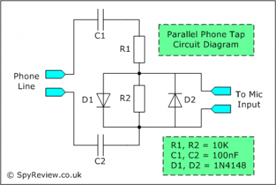
This file contains a schematic for a simple wiretap and instructions for connecting a small tape recorder control relay to the phone line. The discussion begins with an overview of various types of taps, including transmitters, wired taps, and...
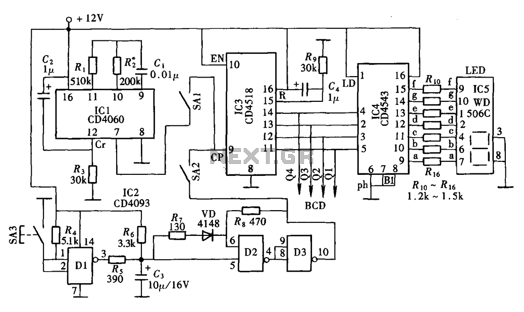
The digital display clock signal source circuit depicted in the figure is derived from a multi-point detection control box within the actual circuit. It primarily comprises an automatic and manual pulse generator, a clock pulse generator, pulse counting elements,...
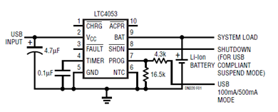
The schematic presented illustrates a minimal component solution for a USB battery charger utilizing the LTC4053 integrated circuit (IC) to create a fully compliant USB charger. This IC functions as a standalone linear charger designed for lithium-ion (Li-ion) batteries,...
The MAX1896, MAX1973, and MAX8863 are integrated circuits that provide output voltages of 5V at 225mA, 1.8V at 220mA, and 3.3V at 60mA, sourced from a USB port. USB devices typically draw power with a voltage range of 4.5V...
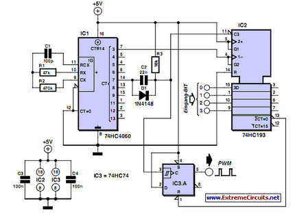
PWM waveforms are frequently utilized to regulate the speed of DC motors. The duty cycle of the digital waveform can be defined using an adjustable parameter. PWM (Pulse Width Modulation) is a technique employed to control the power delivered to...
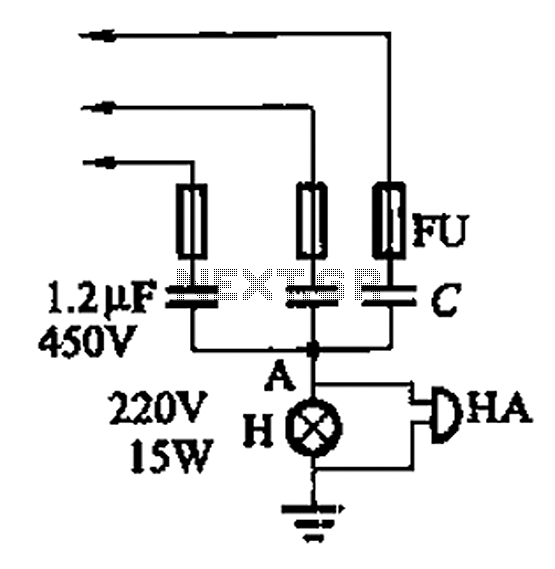
A 3-phase power system poses risks to electrical equipment, particularly asynchronous motors. To detect phase failure, an alarm circuit can be implemented. When the power supply is normal, the voltage at point A is approximately 0V, and no alarm...