
Discrete PWM Generator Circuit

PWM (Pulse Width Modulation) is a technique employed to control the power delivered to electrical devices, particularly in applications involving DC motors. In this context, PWM allows for efficient speed control by varying the duty cycle of the waveform. The duty cycle, expressed as a percentage, represents the proportion of time the signal is in a high state (on) compared to the low state (off) within a given period.
To implement PWM for controlling a DC motor, a microcontroller or dedicated PWM controller generates the waveform. The frequency of the PWM signal must be chosen carefully, generally in the range of a few kilohertz, to ensure smooth motor operation without audible noise. The adjustable parameter, often set via a potentiometer or a digital input, allows the user to modify the duty cycle dynamically.
When the duty cycle is increased, the motor receives more power, resulting in higher speed. Conversely, reducing the duty cycle decreases the power supplied to the motor, leading to a slower speed. This method of control is advantageous because it minimizes power loss compared to other methods, such as resistive control, allowing for more efficient operation and heat management.
In practical applications, additional components may be included in the circuit, such as transistors or MOSFETs, to handle the higher currents required by the motor, as well as diodes for back EMF protection. Proper design considerations, including the selection of appropriate components and the layout of the circuit, are crucial for achieving optimal performance and reliability in PWM-controlled DC motor applications.PWM waveforms are commonly used to control the speed of DC motors. The mark/space ratio of the digital wave-form can be defined either by using an adjusta.. 🔗 External reference
Related Circuits
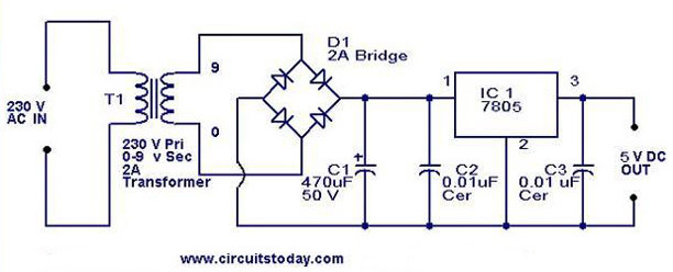
A 5V power supply using IC 7805 is designed and explained with a neat circuit diagram. The circuit for a 5V power supply utilizing the IC 7805 voltage regulator is a straightforward and efficient design that provides a stable output...
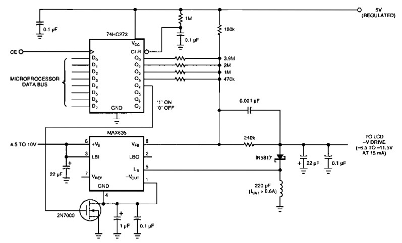
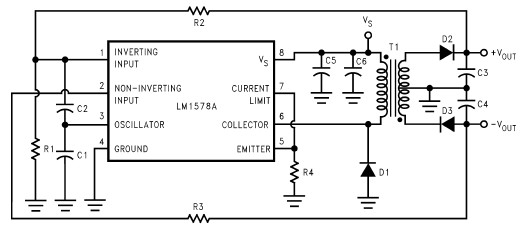
The following figure's switching regulator generates a negative voltage from the notebook battery supply. The microprocessor data bus drives a 4-bit DAC (74HC273), which can vary the regulator output between 6.5 to 11.5 V. This arrangement enables a staircase...
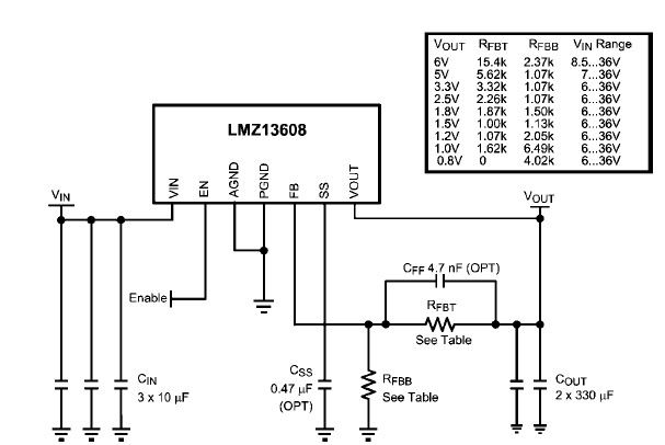
A simple, high-efficiency switching power supply circuit can be designed using the LMZ13608 8A regulator. This regulator offers very high efficiency and requires few external components. It supports a wide input voltage range of 6 to 36 volts and...
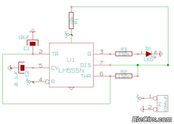
This is a very simple 555 timer circuit that serves as a straightforward theft deterrent, which may be just as effective. The idea is to have a flashing red LED indicate that your car is protected. This device can...
This compact circuit enables automatic recording of phone conversations. It connects to the phone line, the microphone input of a tape recorder, and the remote control jack of the recorder. The circuit detects the voltage level in the phone...
This RS232 power supply circuit diagram is a simple RS-232 line driver power supply that operates from an input voltage as low as 4.2V and delivers an output of ±12V at ±40 mA with an efficiency of better than...