
Phone Tap circuit

In the schematic, the wiretap circuit can be visualized as a series of interconnected components designed to facilitate audio capture from the phone line. The relay serves a crucial role, acting as a switch that engages the tape recorder when a call is made. The wiring diagram should clearly illustrate the connections between the phone line and the relay, ensuring that the signal flows correctly to the recording device.
The potentiometer allows for adjustable volume control, providing flexibility in audio output levels based on the connected device. The capacitor's role is critical; it must be rated adequately to handle the voltage levels present in the phone line while ensuring that it effectively isolates the relay from false triggers caused by normal phone operation.
The audio output transformer is essential for impedance matching between the phone line and the recording device, ensuring optimal signal transfer. The choice of transformer and its configuration may require testing to achieve the best audio fidelity.
Overall, the schematic should be meticulously designed, ensuring that all components are appropriately rated for the intended application, and that the layout minimizes potential interference or signal degradation. Proper labeling of all connections and components will aid in troubleshooting and future modifications.In this file is a schematic for a simple wiretap & instructions for hooking up a small tape recorder control relay to the phone line. First, I will discuss taps a little. There are many different types of taps. There are transmitters, wired taps, and induction taps to name a few. Wired and wireless transmitters mus t be physically connected to the line before they will do any good. Once a wireless tap is connected to the line, it can transmit all conversations over a limited reception range. The phones in the house can even be modifies to pick up conversations in the room and transmit them too!
These taps are usually powered off of the phone line, but can have an external power source. You can get more information on these taps by getting an issue of Popular Communications and reading through the ads. Wired taps, on the other hand, need no power source, but a wire must be run from the line to the listener or to a transmitter.
There are obvious advantages of wireless taps over wired ones. There is one type of wireless tap that looks like a normal telephone mike. All you have to do is replace the original mike with this and it will transmit all conversations! There is also an exotic type of wired tap known as the `Infinity Transmitter` or `Harmonica Bug`. In order to hook one of these, it must be installed inside the phone. When someone calls the tapped phone & *before* it rings and blows a whistle over the line, the transmitter picks up the phone via a relay. The mike on the phone is activated so that the caller can hear all of the conversations in the room. There is a sweep tone test at 415/BUG-1111 which can be used to detect one of these taps. If one of these is on your line & the test # sends the correct tone, you will hear a click. Induction taps have one big advantage over taps that must be physically wired to the phone. They do not have to be touching the phone in order to pick up the conversation. They work on the same principle as the little suction-cup tape recorder mikes that you can get at Radio Shack.
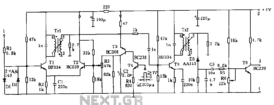
Induction mikes can be hooked up to a transmitter or be wired. A salesman walks into an office & makes a phone call. He fakes the conversation, but when he hangs up he slips some foam rubber cubes into the cradle. The called party can still hear all conversations in the room. When someone picks up the phone, the cubes fall away unnoticed. The 100K pot is used for volume. It should be on its highest (least resistance) setting if you hook a speaker across the output. but it should be set on its highest resistance for a tape recorder or amplifier. You may find it necessary to add another 10 - 40K. The capacitor should be around. 47 MFD. It`s only purpose is to prevent the relay in the phone from tripping & thinking that you have the phone off of the hook. the audio output transformer is available at Radio Shack. (part # 273-138E for input). The red & the white wires go to the output device. You may want to experiment with the transformer for the best output. Hooking up a tape recorder relay is easy. Just hook one of the phone wires (usually red) to the end of one of the relay & the other end just loop around.
This bypasses it. It should look like this: 🔗 External reference
Related Circuits
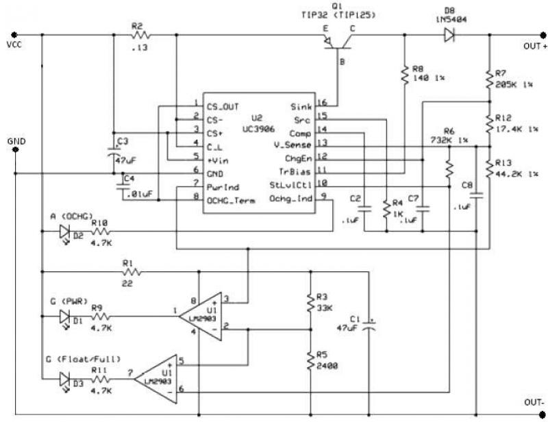
The UC3906 battery charger circuit controller includes all necessary circuitry to manage the charge and hold cycles for sealed lead-acid batteries. This circuit is specifically designed to deliver the appropriate charging voltage and current based on the battery's temperature...
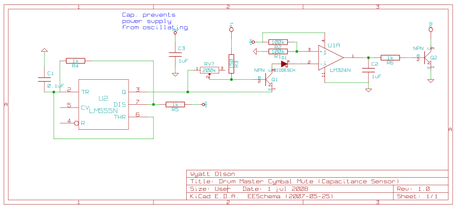
This page contains various small circuits created over time. Some circuits are trivial, while others are more complex, but all are intended to be useful for a variety of projects. Most include both the schematics and the source (KiCad)...
The addition of a mono microphone-level output to the 302 is a beneficial enhancement for connecting transcription recorders, Comtek transmitters, and other inputs. The accompanying diagram demonstrates the correct wiring to create a mono microphone-level output from the tape...
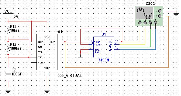
This tutorial explores a common digital concept using the NI Multisim software environment. It examines a four-bit counter that uses a 555 timer IC to generate the clock signal. This tutorial takes less than 30 minutes to complete and...
The circuit operates at a voltage of 9V with a current consumption of only 5mA. It allows for frequency adjustment within the range of 150 to 180 kHz, featuring a bandwidth of approximately 20 kHz. This configuration ensures that...
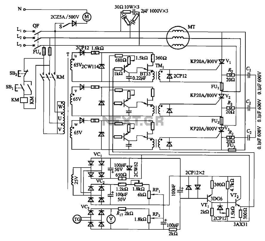
The circuit depicted in Figure 3-181 comprises three thyristors, labeled V1 to V3. The trigger circuit utilizes a single-junction transistor relaxation oscillator. The speed control circuit incorporates negative feedback. A master adjust potentiometer, designated as RPi, is used to...