
HN911L produced by induction lighting

The described circuit operates as a half-wave rectifier that utilizes diodes VD1 and VD2 to convert AC voltage into DC voltage. Capacitor C2 smooths the rectified output to provide a steady 12V source. The transistors VT1, VT2, and VT3 are employed to create a delay function, where VT1 acts as a switch that controls the charging of capacitor C4. The infrared sensor module HN911L is central to the operation, detecting movement through infrared radiation. When motion is detected, the output pin transitions from high to low, triggering a series of actions that result in the illumination of lamp H.
The secondary voltage regulator, connected to VD3, ensures that the voltage supplied to the HN911L module is stable at 6V, which is crucial for its operation. The delay mechanism is vital for applications where prolonged illumination is needed after the motion ceases, such as in hallways or restrooms. The discharge characteristics of capacitor C4, influenced by resistor R4, allow for customization of the delay time, providing flexibility depending on the application requirements.
The light control aspect of the circuit, involving photoresistor R0, allows the system to adapt to ambient light conditions. During the day, the high illumination causes R0 to conduct significantly, preventing the module from activating the lamp. Conversely, as ambient light diminishes in the evening, the resistance of R0 increases, enabling the module to function and potentially illuminate the lamp when motion is detected. The adjustable resistor RP fine-tunes the sensitivity of this light control feature, allowing for further customization based on specific environmental conditions. Overall, this circuit is a practical solution for automatic lighting systems, providing both motion detection and light control functionalities.A simple half-wave rectifier capacitor step-down regulator circuit VD1, VD2, Cl, C2 composition, after power across capacitor C2 available DC voltage of about 12V, the transist or VT1-VT3 composition for delay circuits. This DC voltage VD3 and then by the second voltage regulator and filter capacitor C3 to obtain about 6V stable DC voltage for the integrated module HN911L electricity. When HN911L when the infrared signal is not detected, the second pin output high, vri off, VT2 and VT3 also cut, vs off, electric lamp H does not shine.
When someone close to walking, moving infrared emitted by the human body is received inside the infrared sensor module, the module of the circuit after treatment, a second pin output low, then the PNP-tube VTI conduction, 12V to the positive supply through VT1, VD4 quickly charge the capacitor C4, and VT2 by R4 to the base, so that VT2, VT3 rapid conduction, SCR vs through VT3, R5 obtain trigger current opening, H lamp immediately lights up. As long as people have been nearby activities, beginning Yap helmet lamp H end remains lit. After the man left, the module will return to 2 feet high, VT1 off, but due to the stored charge C4 through R4 to VT2 discharge electrode group, so able to maintain the lighting state of the lamp H.
After about tens of seconds through C4 charge is substantially discharged, sufficient to maintain VT2, VT3 conduction, VT2, VT3 deadline, vs loss of trigger current when the AC zero crossing that is turned off, the lamp H goes out. The delay time of the circuit is mainly determined by R4 and discharge time constant 04, in addition to the resistance R3 and VI2, VT3 the magnification of the circuit delay time is also affected.
Appropriate adjustments to the value of R4 to obtain the appropriate delay time. This circuit can be used for toilet, stairs lighting for walkways and other automatic lighting. Bridging between modules 4,5 feet photoresistor RO and adjustable resistor RP, lamps constituting the light control circuit. During the day due to RO by light irradiation, the resistance is very low, so that the gain of the internal amplifier module greatly reduced, the second leg level at this time without the module output transistor VT1 is not turned on, the lamp will not be lit during the day H.
In the evening, RO resistance becomes high, without much effect on the internal amplifier gain module, so the module can work properly. Adjustment potentiometer RP can adjust circuit light control sensitivity.
Related Circuits
The controller circuit illustrated in Figure 15-24 consists of a switch-type Hall integrated circuit DN838 and an astable multivibrator, which is based on the 555 timer IC. This circuit is suitable for various applications, including automatic door opening, delay...
This project is intended for controlling mains powered disco lighting, although there are many other possible uses for controlling almost any mains appliance. It will control five separate channels at up to 3 Amp per channel. This could be...
The success or failure of lighting upgrades depends on the quality of components and workmanship. Proper wire routing is essential to prevent insulation chafing. The quality of soldering connections is crucial, as poor solder joints can corrode and fail....
A highly practical workbench lighting unit designed for electronics hobbyists. The portable inspection lamp circuit features an onboard voltage regulator and a high-brightness 5mm white LED. It can be powered by any 9 to 18 volt DC-rated AC mains...
After being careful about every orientation of every transistor, a circuit board was designed around the LM387N, which was not the intended chip nor the one originally ordered (LM258, commonly referred to as LM358). During testing before adding larger...
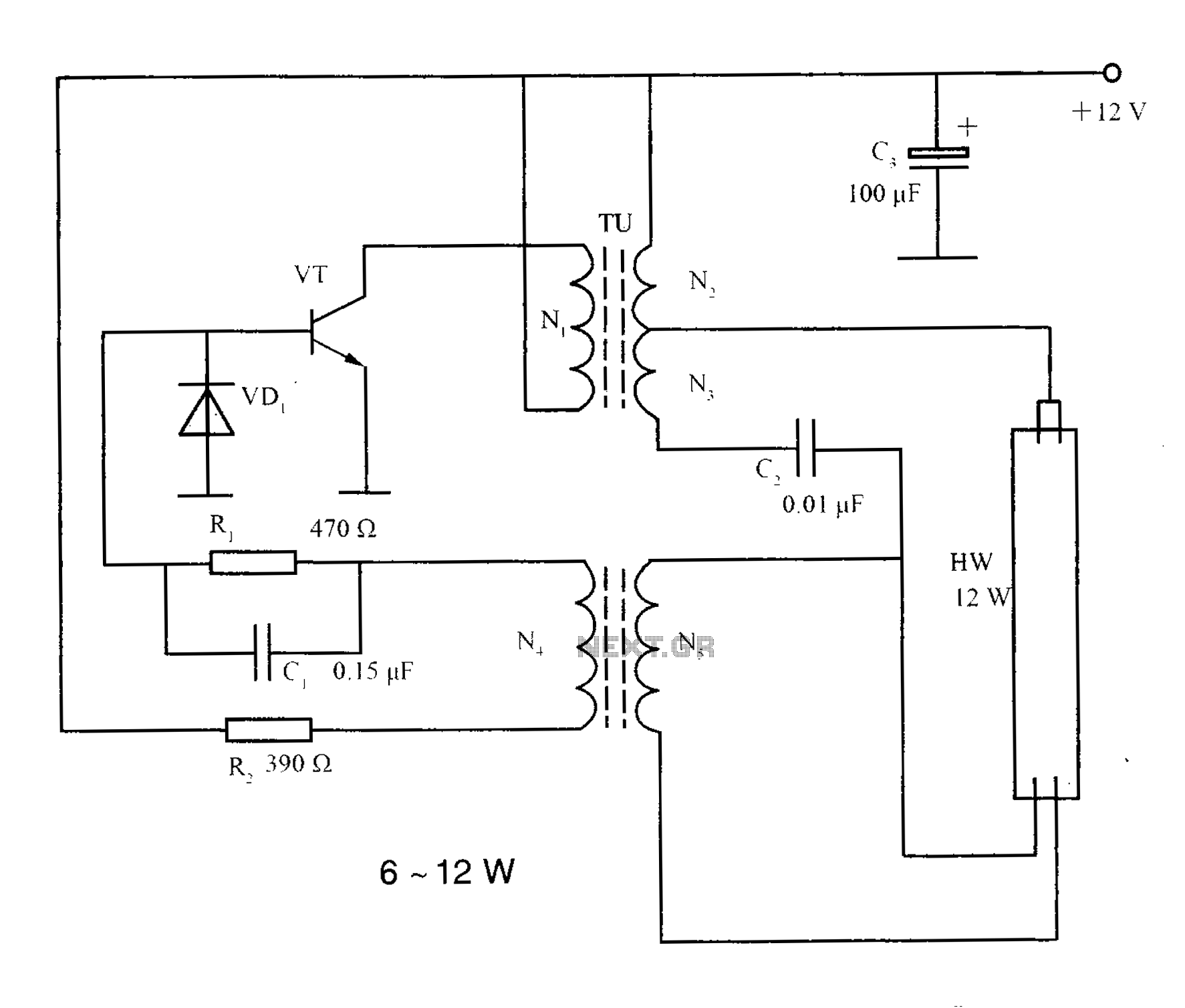
The lighting inverter circuit is designed for 6 to 12W fluorescent lamps. It operates by first bucking the mains voltage, followed by rectification and filtering to charge a battery. When the inverter is activated, it generates a high-frequency alternating...