
555 alarm doorbell and lighting controller circuit

The controller circuit features a Hall effect sensor (DN838) that detects magnetic fields and can be activated by a magnet. When the sensor is triggered, it sends a signal to the astable multivibrator, which generates a continuous square wave output. The 555 timer in astable mode is configured with resistors and capacitors, determining the frequency and duty cycle of the output signal.
In automatic door opening applications, the Hall sensor can be positioned near a door frame, and when a user approaches with a magnet (e.g., on a key fob), the door can be programmed to open automatically. For delay alarms, the output from the 555 timer can be used to trigger an audible alarm after a predetermined time, providing a warning before activation.
The circuit can also control lighting systems by using the astable multivibrator to turn lights on and off automatically, based on the presence of a magnetic field detected by the Hall sensor. This feature is beneficial for energy-saving applications. Additionally, the circuit can function as a doorbell, where the Hall sensor detects the presence of a visitor and activates a chime or buzzer.
Overall, the combination of the Hall integrated circuit and the astable multivibrator provides a versatile and efficient solution for various automation tasks in residential and commercial settings.As the figure 15-24 shows, the controller circuit is composed of the switch type Hall integrated circuit DN838 and the astable multivibrator (composed of the 555), this circuit can be used in wide range of applications such as the automatic door opening, automatic delay alarm, automatically turns off the lights and also it can be used as the doorbell. The a.. 🔗 External reference
Related Circuits
The Audio Automatic Gain Control (AGC) circuit monitors the output signal level of an audio preamplifier. When the input signal increases, the AGC circuit automatically reduces the amplifier's gain. Conversely, when the input signal decreases, the AGC circuit increases...

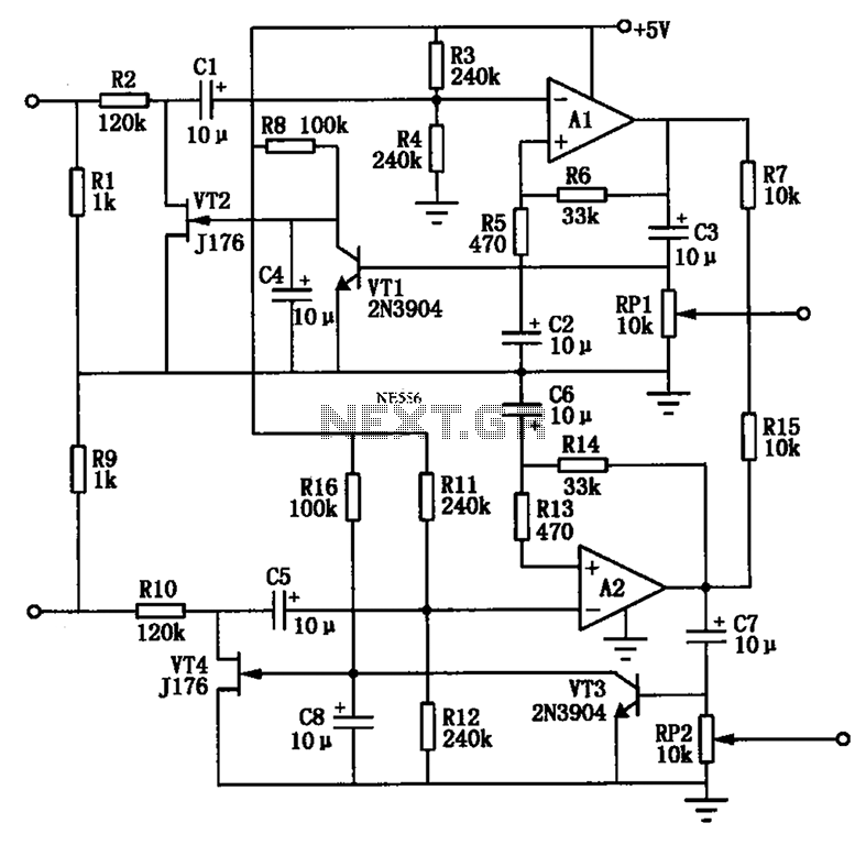
The schematic diagram illustrates the temperature sensor that is set to be launched. The LM135 sensor, functioning as a Zener diode, is connected via a foot-long cord to the circuit through a plug. This design allows the sensor to...
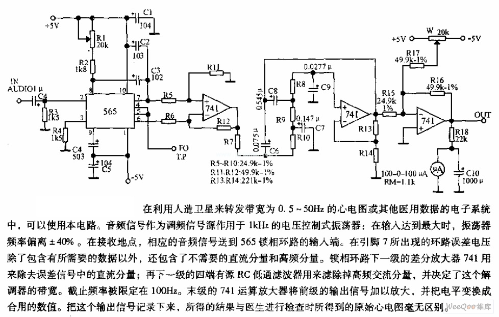
The circuit is designed for satellite transmission of ECG signals with a bandwidth range of 0.5 to 50 Hz, as well as other medical data within electronic systems. An audio signal serves as the FM signal source, which is...

A resistor R1, capacitor C1, and two converters create a square wave generator that produces a fundamental tone. This generator is followed by an inverter that functions as both a buffer and a driver for the system. Resistor R2,...
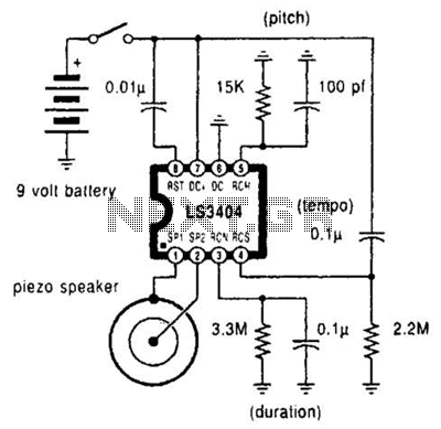
A high-quality melody circuit produces a slow decay waveform that generates chime-like notes. The pitch, tempo, and duration of the notes are all adjustable. The melody circuit is designed to offer a versatile sound generation capability, making it suitable for various...
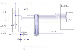
The dual-channel thermometer is a simple project based on a PIC microcontroller with ADC capabilities. It is an inexpensive thermometer that utilizes low-cost components and does not require high-sensitivity or expensive sensors. Instead, it employs a simple silicon diode...