
disco lighting

This project employs a triac-based control system for managing mains-powered lighting, specifically tailored for disco applications. The design features five independent channels, each capable of handling a load of up to 3 Amperes. This load capacity can be enhanced by creating an alternative printed circuit board (PCB) with wider trace widths, accommodating higher currents if necessary.
The choice of triacs over traditional relays is significant in this application. Triacs provide rapid switching capabilities and operate silently, eliminating the mechanical noise associated with relay actuation. This is particularly advantageous in environments where sound quality is critical, such as in disco settings.
To ensure safety and reliability, the design incorporates opto-couplers that provide electrical isolation between the low voltage control circuitry and the high voltage mains side. This isolation is crucial for protecting the control circuitry from voltage spikes and ensuring user safety when interfacing with high voltage systems.
The absence of a detailed schematic is noted, but the simplicity of the project allows for straightforward implementation. The included PCB is designed to facilitate easy assembly and integration, making it accessible for both hobbyists and professionals looking to control lighting or other mains appliances. The overall design emphasizes efficiency, safety, and performance, making it a versatile solution for various applications beyond disco lighting.This project is intended for controlling mains powered disco lighting, although there are many other possible uses for controlling almost any mains appliance. It will control five seperate channels at up to 3 Amp per channel. This could be increased by designing another PCB with wider tracks than the PCB included with this design.
I could have used relays to control my lights, but triacs seemed like a more sensible solution as they react quicker and are totally silent as they contain no mechanical parts. The low voltage control side and the mains side are totally isolated, as opto-couplers are used to fire the triacs. I have not included any schematics as this project is very simple, expecially due to the fact I have included a PCB.
Notes: There isn&# 🔗 External reference
Related Circuits

The T-40-16 and 555 ultrasonic transmitter circuit configuration consists of an ultrasonic transmitter T-40-16 and a 555 timer circuit. By adjusting the potentiometer RP, the oscillation frequency of the circuit can be changed. The output pulse frequency from the...

This application note discusses the use of SEPIC power modules to supply the necessary power for driving high-brightness LED arrays. These arrays serve as display backlights and necessitate a wide dimming range. The SEPIC configuration offers an efficient and...
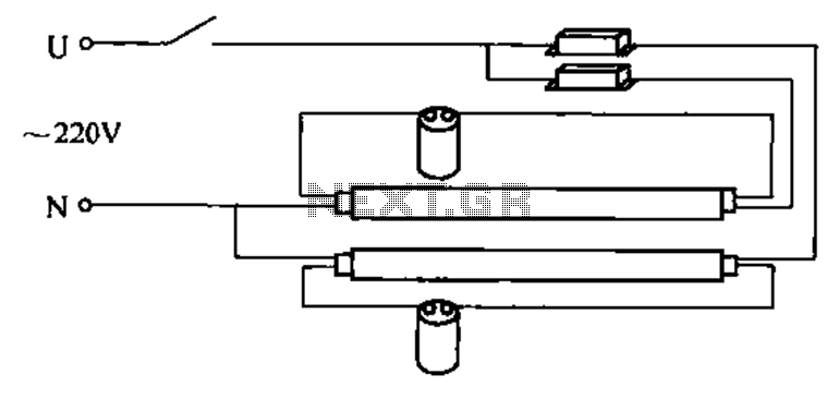
A double tube fluorescent lighting circuit is illustrated. In certain situations, a single tube light may not fulfill the lighting requirements, necessitating the use of double tube lighting. The physical installation is depicted in the circuit of a double...

The core device is a circuit pyroelectric infrared sensor (BH). When it detects infrared radiation from a body, the sensor element responds to changes in temperature. As a thermoelectric element, its self-ferroelectric polarization value changes, causing a discharge of...

The controller circuit illustrated in Figure 15-24 consists of a switch-type Hall integrated circuit DN838 and an astable multivibrator, which is based on the 555 timer IC. This circuit is suitable for various applications, including automatic door opening, delay...

Deep discharge can damage a rechargeable battery. By disconnecting the battery from its load, this circuit halts battery discharge at a predetermined level of declining terminal voltage. Transistor Q1 acts as the switch. The overall circuit draws about 500µA...