Home Made Metal Detector

This homemade metal detector circuit will assist in locating objects made from materials that possess relatively high magnetic permeability. It is not appropriate for detecting...
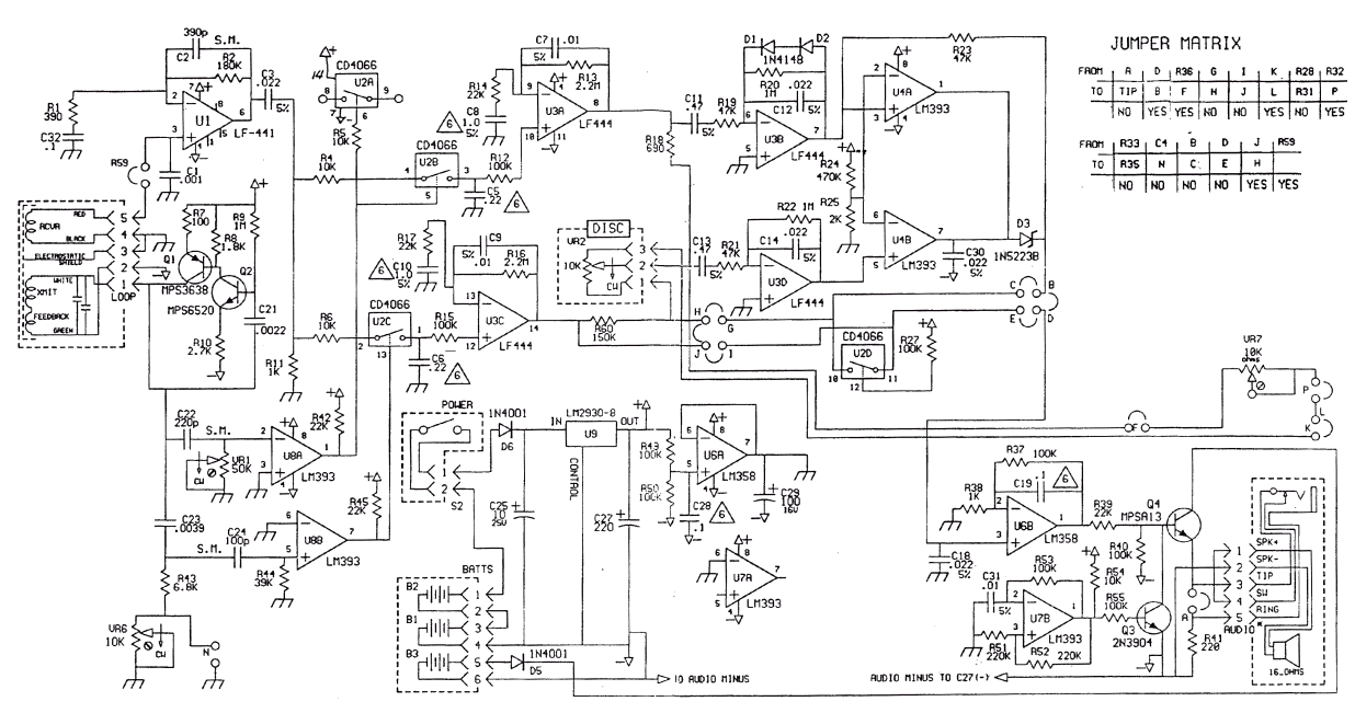
This homemade metal detector circuit is designed to identify objects composed of materials such as iron, nickel, and cobalt, which exhibit high magnetic permeability. The circuit typically consists of a few key components: an oscillator, a coil, and a detector.
The oscillator generates a high-frequency alternating current (AC) signal, which is fed into a coil. This coil acts as an inductor, creating a magnetic field around it. When the circuit is in operation, the magnetic field interacts with nearby metallic objects. If an object with high magnetic permeability enters the magnetic field, it alters the field's characteristics, causing a change in the inductance of the coil.
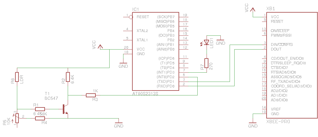
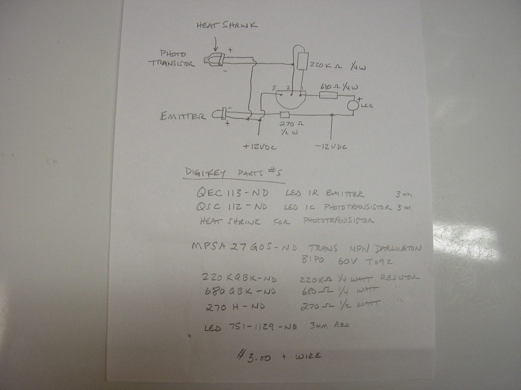
This change can be detected by the circuit's detector, often implemented using a transistor or operational amplifier. The detector processes the variations in the signal and produces an output that can be used to trigger an alarm or light indicator, alerting the user to the presence of metal.
For optimal performance, the circuit may require calibration to account for environmental factors and the specific materials being detected. Power supply considerations are also essential; typically, a battery is used to ensure portability and ease of use.
In summary, this metal detector circuit is a practical project for electronics enthusiasts, providing an accessible means to explore the principles of electromagnetism and signal processing while enabling the detection of ferromagnetic materials.This homemade metal detector circuit will help you find objects composed of materials with relatively high magnetic permeability. It is not suitable for b.. 🔗 External reference


