
Home Security System

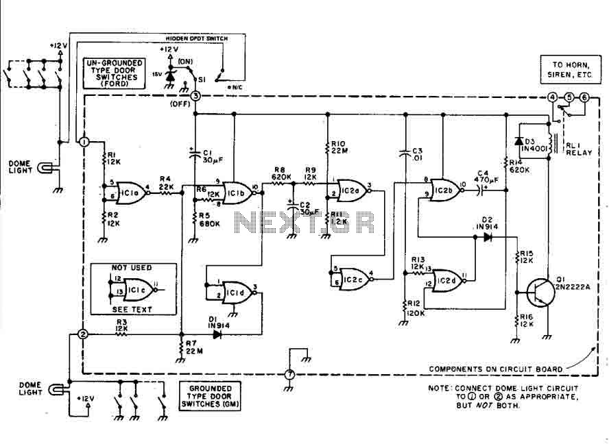
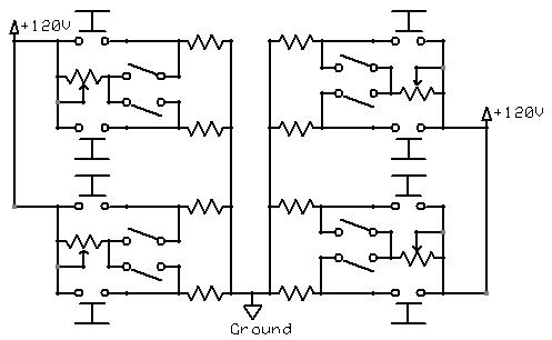
The described alarm circuit employs a series of switches (S1 to S5) that, when activated, initiate the alarm sequence. The activation of these switches sends a signal to LED1, which serves as a visual indicator of the alarm status. The signal is further processed by integrated circuits IC1C and IC1D, which control the operation of transistor Q1. This transistor acts as a switch to energize relay RY1, allowing it to latch and maintain the alarm state even after the initial activation signal is removed.
The self-latching feature of relay RY1 ensures that once the alarm is triggered, it remains active until a reset command is issued. This is accomplished through switch S10, which, when engaged, interrupts the current flow and resets the circuit to its initial state.
In scenarios where the key switch S1 is activated or the re-entry buttons S6 are pressed, the circuit design incorporates a delay mechanism through an RC network made up of resistor R7 and capacitor C3. This configuration temporarily deactivates IC1C, preventing immediate reactivation of the alarm. The time it takes for the capacitor C3 to charge through resistor R7 determines the delay period before the alarm can be re-engaged.
Overall, the alarm circuit is designed for reliability and user control, allowing for quick resets while preventing accidental reactivation during authorized re-entry situations. The combination of visual indicators, latching mechanisms, and delay circuits enhances the functionality and usability of the alarm system in various applications. This alarm circuit activates when SI through S5 are activated. This lights LED1 and activates Ql via IC1C and IC1D. RY 1 is wired to self latch. S10 is used to reset. When key switch SI is activated or when re-entry buttons at S6 are depressed, IC1C is deactivated until RC network R7/C3 charges.
Related Circuits
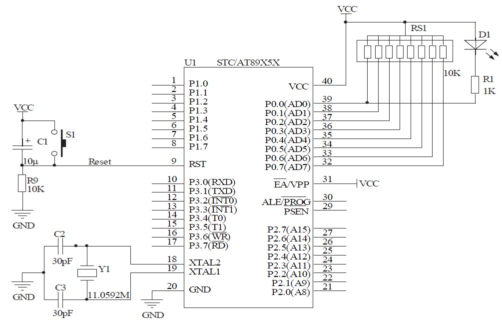
This document will present an overview of two critical components within a one-chip computer: the timing/counter system and the interrupt system. Through this explanation, readers will gain insight into the operating principles of these systems. For illustration, consider an...
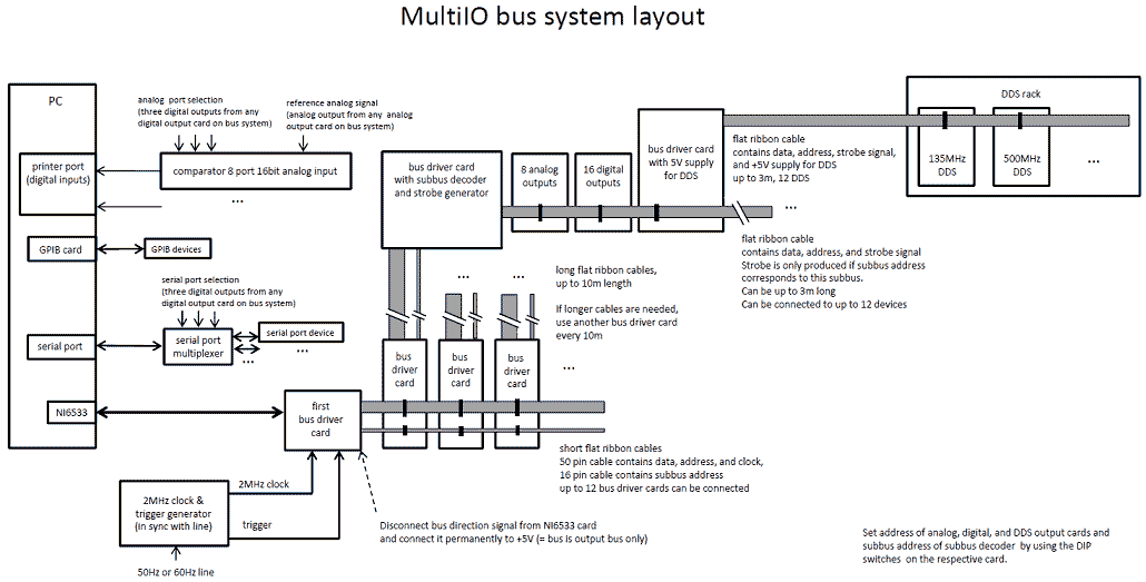
We have developed a powerful yet inexpensive and easy to construct experiment control system. The construction of the system together with the control software is described here. All circuits and software are free to download and use for nonprofit....
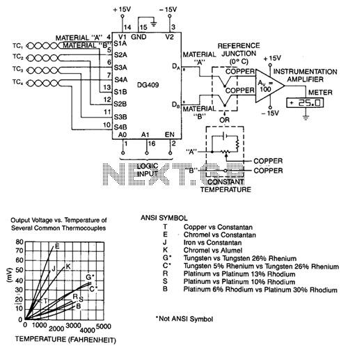
To decouple the sensors from the meter amplifier, either a reference junction at 0°C or a bucking voltage set at room temperature may be used. The latter method is simpler but is sensitive to changes in ambient temperature. The...
This car alarm circuit features an 18-second delay for both entrance and exit. It sounds continuously for 6 minutes before automatically turning off the horn and preparing for the next triggering event. The alarm remains activated even if the...
The momentary switch utilized has a safety rating of 10A. If a switch is rated for a current that is too low, the instantaneous current during the first millisecond could cause the switch contacts to fuse together. To achieve...
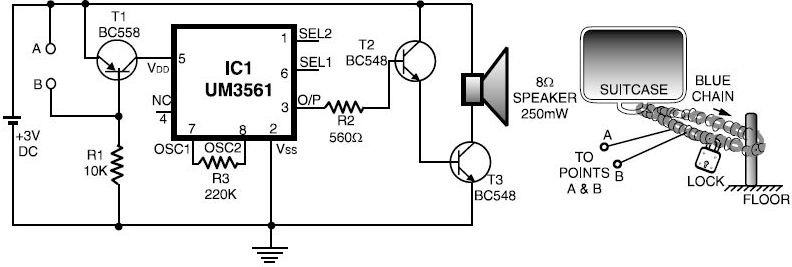
This luggage or bike alarm can be utilized while traveling by train or bus. Typically, luggage is secured using a chain-and-lock arrangement; however, there are still vulnerabilities. The luggage or bike alarm system is designed to enhance the security of...