
Luggage Bike Security Alarm Circuit

The luggage or bike alarm system is designed to enhance the security of personal belongings during travel. It operates by integrating a motion sensor with an audible alarm. When the luggage or bike is tampered with or moved unexpectedly, the motion sensor detects the disturbance and triggers a loud alarm, alerting the owner and deterring potential thieves.
The system typically consists of the following components: a microcontroller, a motion sensor (such as a passive infrared sensor or an accelerometer), a loudspeaker or buzzer for the alarm, a power supply (usually batteries), and a locking mechanism that can be integrated with the existing chain-and-lock setup.
The microcontroller serves as the central processing unit, receiving input from the motion sensor and controlling the alarm output. The motion sensor is strategically placed on the luggage or bike to maximize its sensitivity to any unauthorized movement. The alarm can be set to various sensitivity levels, allowing users to customize the response based on their environment.
Power management is crucial for this device, especially for portable applications. The use of low-power components and sleep modes can extend battery life, making the alarm more practical for long journeys. Additionally, some systems may include features such as remote notifications via a smartphone app, allowing users to monitor the security of their belongings in real-time.
In conclusion, this luggage or bike alarm provides an effective solution for travelers seeking to protect their possessions. Its integration with traditional locking methods enhances security, while its alarm functionality offers peace of mind during transit.This luggage or bike alarm can be used while travelling by trains or bus and we generally lock our luggage using a chain-and-lock arrangement. But, still w.. 🔗 External reference
Related Circuits
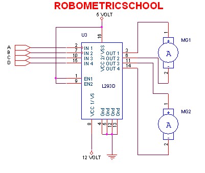
The electronic schematic of a DC motor driver using the L293D, as illustrated in Figure 2, enables the control of two DC motors continuously. It allows for one motor to rotate clockwise while the other rotates counterclockwise. Additionally, all...
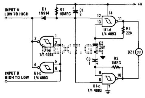
When a printer is shut down, an alarm is triggered. The input can be either a high-to-low or low-to-high transition. This corresponds to the logic level indicating whether the printer is on or off. The oscillator generates an interrupted...

This car audio amplifier circuit is based on the LA47536 audio amplifier integrated circuit designed by Sanyo. This audio amplifier circuit is specifically designed for car audio power amplifiers. The LA47536 car audio amplifier IC features four output channels...

This is a simple design of an audio level meter. The circuit utilizes a single integrated circuit (IC) and a minimal number of external components. It is based on the LM3915, which functions as the controller for the audio...
The digital scoreboard circuit is designed to display numerical values ranging from 0 to 9 on a common anode 7-segment display. The circuit employs a 7-segment driver integrated circuit (IC), specifically the 74LS47 or 74LS247. A 555 timer IC...
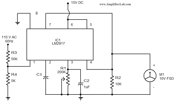
The circuit diagram of a simple capacitance meter is presented here. The primary component of this circuit is the frequency-to-voltage converter. The simple capacitance meter circuit utilizes a frequency-to-voltage converter as its central element to measure capacitance values. This circuit...