
Homebuilt Hellschreibers

The described circuitry integrates multiple components for efficient operation. The tone detector is designed to identify specific audio frequencies, which triggers the solenoid driver circuit. The solenoid driver utilizes a solid-state relay for reliable switching, while the flyback diode safeguards against voltage spikes, ensuring the longevity of the components.
For motor speed control, a feedback loop is implemented, allowing real-time adjustments based on the output from the optical sensor. The sensor's infrared LED and phototransistor work in tandem to detect the rotation speed of the spindle, providing valuable data for the control system. The adjustment mechanism for the spindle speed, which can be achieved through various methods, emphasizes the importance of precision in applications where print quality is critical.
The calibration process for the paper transport speed is straightforward, requiring minimal tools and effort. The use of a tachometer or an optical sensor simplifies the task of achieving the desired speed, ensuring accurate and consistent operation. The choice of materials for the ink roller, such as felt pads, reflects a practical approach to component selection, ensuring effective ink application during operation.
In summary, the described electronic circuitry is designed for efficient control of a tone detection and printing system, integrating various components for optimal performance. The methods for calibration and adjustment ensure that the system operates within specified parameters, resulting in high-quality output.The circuitry for the tone detector, solenoid driver, and motor speed control (paper transport and spindle) is rather straightforward. A solid-state implementation of the driver circuit typically needs a diode (installed with reversed polarity) across the magnet solenoid, to avoid damage due to the inductive voltage spike upon de-energizing the solenoid.
This is referred to as a flyback, snubber, freewheeling, catch, or suppressor diode. If the relay is a bit slow when energized, you may try to speed it up with one of the simple circuits described here. They basically briefly apply almost twice the supply voltage to the relay coil when energizing. The capacitor in the circuit will have to be adapted to the desired speed and relay (decay time). Paper transport speed calibration is easy: all you need is a stopwatch and a ruler or tape measure. Simply adjust the motor rpm to obtain about 47 cm per minute. Unlike the spindle in a Feld-Hell machine, my spindle is a single-thread (1-start) worm. It needs to turn at 7 columns per character x 2 ½ characters per sec x 60 sec/min = 1050 rpm. The Feld-Hell machine has a double-thread (2-start) spindle: it has two intertwined windings. Note that the number of threads is not related to the number of turns of each thread! Both the Feld-Hell and my homebuilt spindle have two turns. The Feld-Hell spindle only needs to turn at ½ x 1050 = 525 rpm, to get the same effect as a single-thread spindle at 1050 rpm.
Adjusting the spindle speed to 1050 rpm can be done several ways: 1) first get the electro-magnet to work properly (which you have to do anyway, hi), then feed the printer with "known-good" Hell-audio and adjust the rpm until the print becomes legible and the text lines are horizontal; or 2) use a tachometer. I used method nr. 2 by building a very simple optical sensor (4 cheap components), attaching a strobe disk to the spindle shaft with a dab of glue, and measuring the sensor output signal with an oscilloscope.
You can make a crude strobe card with a black felt marker, but such markers are really not black at all, and the ink does not have good reflectivity. Best is to print one on regular paper with a laser printer. Here is a file with strobe disks that have 1, 2, and 4 black segments and ±5 cm (2") diameter. The sensor simply consists of an infrared LED and a phototransistor. No specific types (you can also use an IR diode + transistor in a single package, e. g. , an SY-CR102). I shielded them with shrink tube (black on the 5 mm LED, blue on the 3 mm phototransistor in the photo below).
As you can see in the photo, I bent the leads such that the diode and transistor are not parallel, but are trained at a point just in front of them (about 2-3 cm, 1"). The largest swing in the sensor output signal (5 Vpp) was observed at a distance of 0. 8-1 cm ( ±3/8") from the strobe disk. The scope image below indicates that the spindle is turning at 1500 rpm, and needs adjustment. A period of 10 msec (100 Hz) = 100 cycles per second, and 4 black segments on the strobe card means 100/4=25 rps which is 25x60=1500 rpm.
The scope is set to AC-coupling. The ink-roller is made of several round felt pads that I stacked, glued together, and drilled a hole through the center. The pads are simply felt bumper-feet for furniture (the ones with adhesive backing are the easiest), available in several forms at your local Do It Yourself store.
An other option is a felt polishing wheel (or tip) from a Dremel ® type rotar 🔗 External reference
Related Circuits
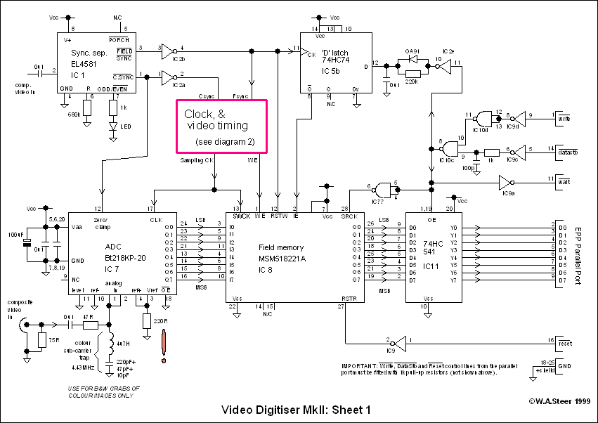
A video digitizer, also known as a frame grabber, captures still picture frames from a television set, video camera, or video recorder, and transmits them to a computer for display, storage, or manipulation. This document outlines the Mark II...
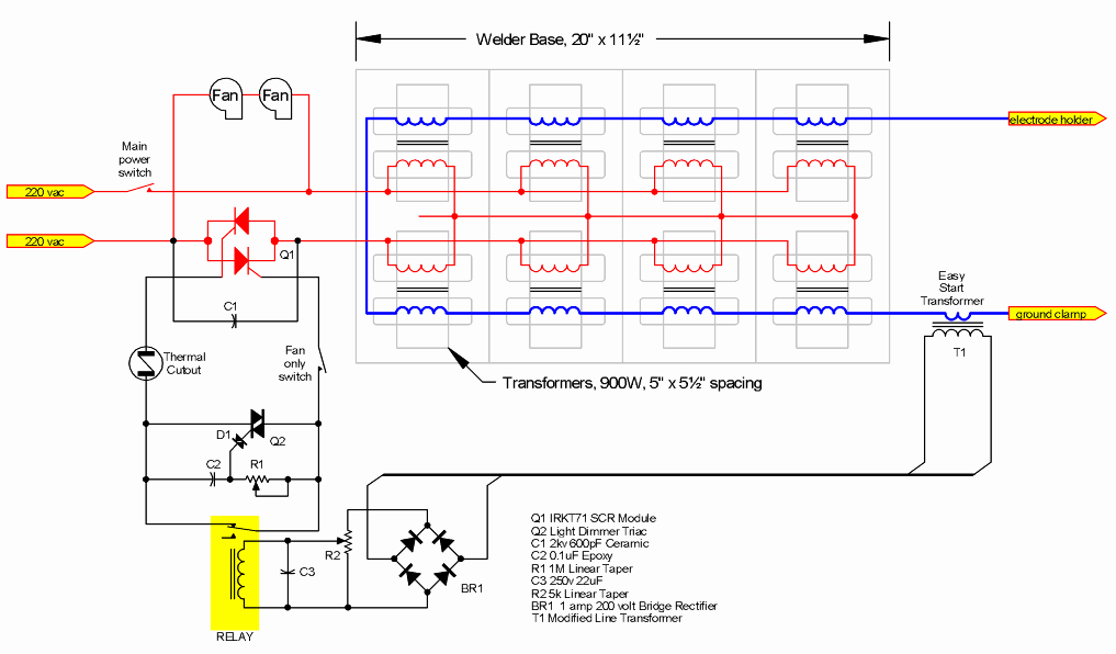
Construct a personal arc welder. Many individuals have eagerly anticipated the release of these comprehensive plans, which are available for purchase and download in a 4.6MB PDF file for a nominal fee. The arc welder is a vital tool in...
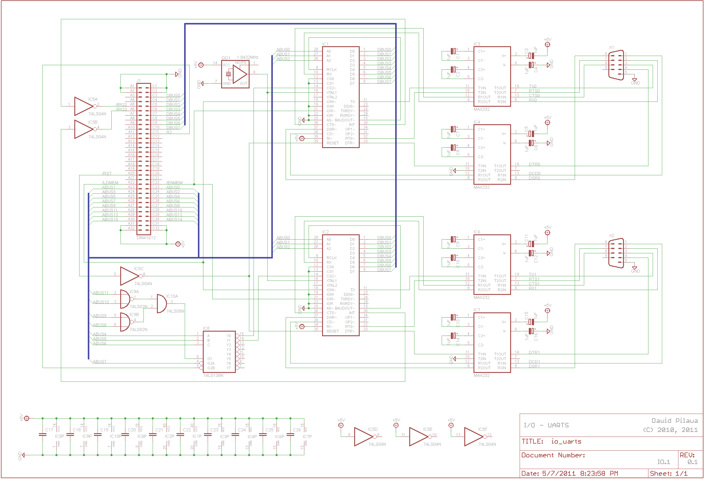
A functional interrupt-driven RS/232 driver is currently in operation, supporting hardware flow control at a baud rate of 9600 bps. Although higher baud rates are achievable, stability has yet to be verified. Helper routines have been developed to facilitate...
There is enough of poorly constructed RS232 alike TTL level interfaces (+5volt), this one generates its own +/- 10..11 volts as RS232 specs require, and is able to use very long cables like RS232 can, and protects computer as...