
Honda Motorcycle CB400 (Hawk II) Wiring Diagram
")
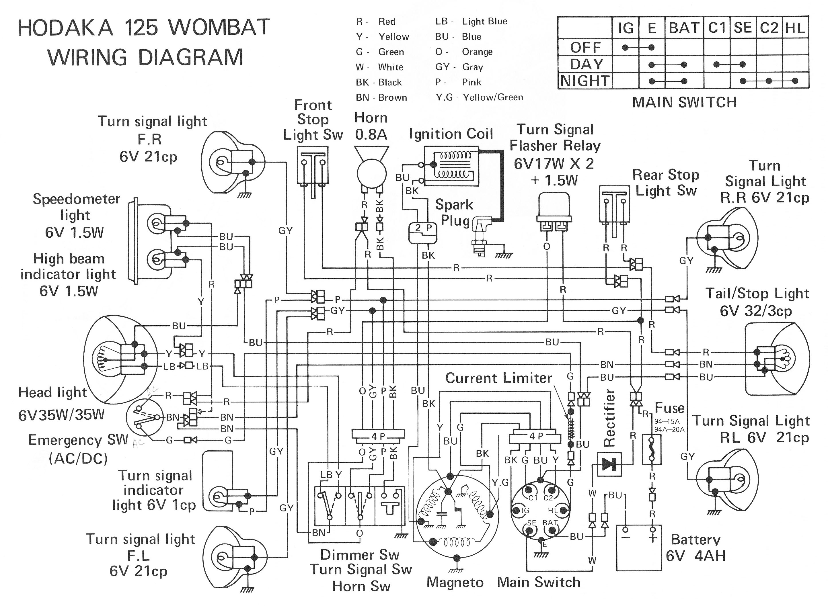
The electrical wiring connection diagram for the Honda Motorcycle CB400 (Hawk II) serves as a crucial reference for understanding the interrelated components within the motorcycle's electrical system. This schematic provides a visual representation of the wiring layout, allowing for easier troubleshooting, maintenance, and modifications.
The diagram includes essential elements such as the turn signal and emergency stop switch, which are vital for rider safety and vehicle signaling. The starter button and starter magnetic switch are integral to the engine ignition process, ensuring reliable starting of the motorcycle. The capacitor discharge ignition unit plays a significant role in delivering high-voltage sparks to the spark plug, facilitating efficient combustion in the engine.
Indicators such as the oil pressure warning light, neutral indicator, and high beam warning light enhance rider awareness of the motorcycle's operational status. The inclusion of the speedometer light ensures visibility of the speedometer readings during low-light conditions. The headlight and tail light circuits are critical for visibility and safety on the road, while the flasher relay manages the operation of the turn signals.
Additional components, such as the alternator and regulator rectifier, are responsible for generating and regulating electrical power, ensuring that the battery remains charged and that the motorcycle's electrical system operates smoothly. The wiring diagram also highlights the connections for the horn and oil pressure switch, which contribute to both safety and performance.
The presence of a color code and diagram key further enhances the utility of the schematic, providing clarity on wiring connections and facilitating easier identification of components. This comprehensive wiring diagram not only aids in the assembly and repair of the motorcycle but also serves as an educational tool for those interested in understanding the electrical workings of the Honda CB400 (Hawk II).The following picture shows the electrical wiring connection diagram for Honda Motorcycle CB400 (Hawk II). It shows the connection between Honda parts such as the turn signal, emergency stop switch, starter button, spark plug, capacitor discharge ignition unit, turn signal indicator, oil pressure warning light, neutral indicator, high beam warning
light, speedometer light, headlight, tail light circuit, ignition switch, clutch switch, dimmer switch, horn button, oil pressure switch, horn, neutral switch, alternator, regulator rectifier, starter motor, starter magnetic switch, battery, tail and brake light, flasher relay, capacitor discharge ignition unit, and many more. Color code and diagram key also available. 🔗 External reference
Related Circuits
Also known as the Free lamp (commonly referred to as the Myanmar lamp by online sellers), this device operates using the voltage from a standard household fixed telephone line, eliminating the need for batteries or AC power. The lamp...

Electronic FM Telephone Transmitter Schematic. The following schematic design illustrates a circuit diagram for an FM telephone transmitter built on a compact PC board layout. This small design allows it to be easily integrated within the housing of a...
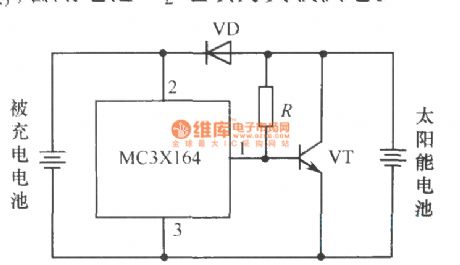
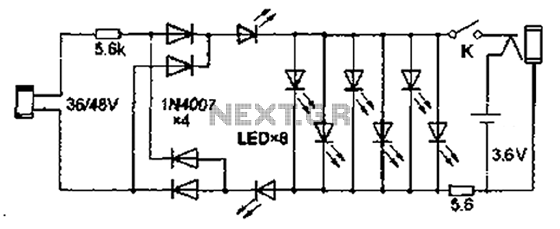
The following circuit illustrates a current-limited solar battery charger circuit diagram. This lead-acid or Ni-Cd battery charger circuit diagram utilizes solar energy to charge a 6-volt, 4.5 Ah rechargeable battery for various applications. It represents a straightforward solar battery...
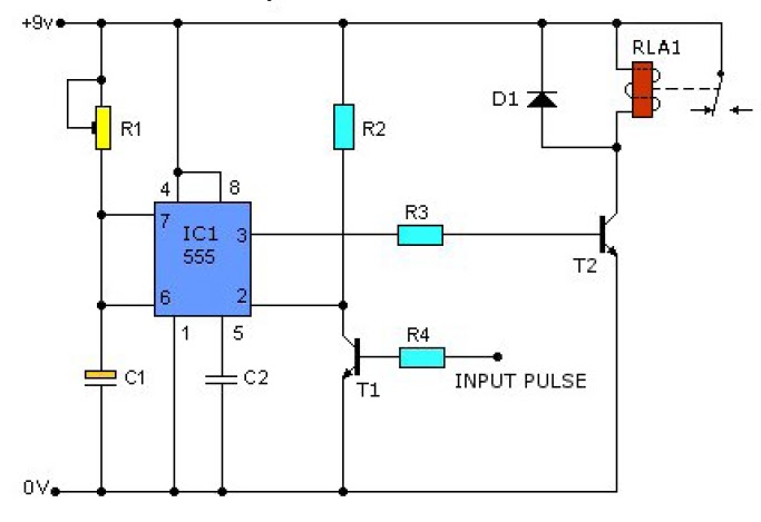
This causes T1 to conduct, pulling pin 2 of IC1 low. IC1 then enters a timing cycle, the duration of which is set by R1 and C1, resulting in pin 3 of IC1 going high. This action causes T2...
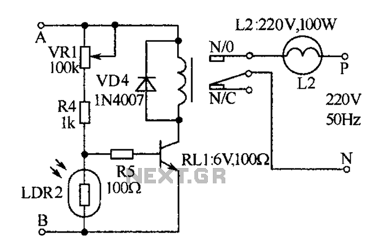
The receiver, as depicted in the figure, assists patients in avoiding missed audio signals during the daytime. The receiver operates independently, and the lighting will automatically turn off. At night, the lighting signal receiver activates simultaneously with the patient's...
Electronic Schematic Circuit Diagrams Manual PDF Download. The document provides a comprehensive manual that focuses on electronic schematic circuit diagrams. These diagrams are essential tools for understanding and designing electronic circuits, offering visual representations of circuit components and their interconnections....