
555 pulse timer circuit diagram basic

The circuit described operates using two transistors, T1 and T2, along with an integrated circuit (IC1) that functions as a timer. The operation begins when T1 is activated, which pulls the voltage at pin 2 of IC1 to a low state. This low state triggers IC1 to enter its timing cycle, the duration of which is determined by the resistor R1 and capacitor C1 connected to it. The RC time constant established by these components dictates how long pin 3 of IC1 remains high after T1 is triggered.
Once pin 3 of IC1 goes high, it activates T2, allowing current to flow through it. This action can be used to drive a load or trigger another part of the circuit. After the timing cycle concludes, T2 turns off, halting the current flow until T1 receives another pulse, thus restarting the cycle.
For component replacements, T1 can be substituted with either ECG123AP or NTE123AP transistors, ensuring that the device is rotated 180° to match the original lead configuration. Similarly, T2 can be replaced with ECG123A or NTE123A transistors, maintaining circuit integrity and functionality. The design is straightforward, making it suitable for various applications where timing and control are essential.This causes T1 to conduct, taking pin 2 of IC1 `low`. IC1 then enters a timing cycle, the duration of which is et by R1/C1, causing pin 3 of IC1 to go`high`. This causes T2 to conduct. At the end of the timing cycle T2 switches off, and the circuit waits for the next pulse toT1. T1 replacements: ECG123AP or NTE123AP (Rotate device 180 ° to conform w ith original lead configuration). T2 replacements: ECG123A or NTE123A. 🔗 External reference
Related Circuits
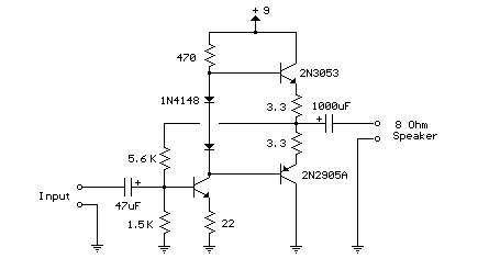
This weblog focuses on electronic circuit schematics, PCB design, DIY kits, and electronic project diagrams. The following describes a small audio amplifier, similar to those found in medium-sized transistor radios. The input stage is biased to ensure equal power...
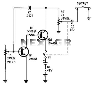
Useful for troubleshooting audio, video, and lower frequency RF amplifiers. This circuit generates a signal that is rich in harmonics. The circuit designed for troubleshooting audio, video, and lower frequency RF amplifiers is crucial for diagnosing issues in these systems....
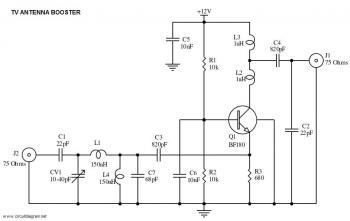
This is a straightforward circuit for a UHF band TV antenna booster that provides a gain of 15 dB. This low-cost antenna booster is simple and easy to construct. The UHF band TV antenna booster circuit is designed to enhance...
The modular Portable Mixer design presented on these web pages has gained popularity among many amateurs. However, some users have requested a simpler device specifically for mixing mono signals. This revised design aims to meet those requirements, incorporating three...
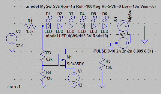
A suitable method to sense when some LEDs in a garage door opener are illuminated. A power source, potentially the same as Vout, connects to a 1.5 kΩ resistor, which then connects to six LEDs followed by a transistor....

Figure 1-122 is a dedicated high-fidelity surround sound processing integrated circuit (IC) TDA3810 circuit that manages surround sound. The stereo signal is processed through input coupling capacitors C1 and C2. The internal buffer amplifier handles the left and right...