
Honey Bee Counter Circuit

The described circuit operates on a dual-sensor system that detects the movement of bees through a designated gate. The real-time clock is programmed to deactivate the counting function during nighttime hours, thereby minimizing power consumption. The core of the system involves an LED that illuminates the pathway, and a phototransistor that detects the reflected light. This reflection indicates the presence of a bee passing beneath the LED.
The alignment of two sensors allows for directional detection of the bees. When a bee approaches the gate, it will first interact with one of the sensors. If the inside sensor is triggered first, it indicates that the bee is exiting the area; conversely, if the outside sensor is activated first, it indicates that the bee is entering. This functionality is crucial for monitoring bee activity and can be used for various research or agricultural applications.
The sensitivity of the phototransistor is adjustable through the use of resistors connected to ground. The choice of a 100k ohm resistor is significant as it optimizes the sensitivity of the circuit, allowing for reliable detection of the bees. If a resistor with a lower resistance value were used, the circuit would become less sensitive, potentially leading to missed detections. The NPN phototransistor serves as the light sensor, converting the incident light into an electrical signal that can be processed by the Arduino or Teensy microcontroller.
In summary, this circuit effectively combines a real-time clock, phototransistor sensors, and a microcontroller to create a responsive and energy-efficient monitoring system for bee movement. The design considerations regarding sensitivity and sensor placement are critical for the accurate functioning of the system.Real time clock turns OFF the counter at night for reduced power. When the bee crosses under the LED the light is reflected back to the sensor. (its a photo transistor) and triggers a digital input to the Arduino. (or teensy in my case). I lined up two chips right ne xt to each other. as the bee goes through the gate if it hits the inside sensor first. its going out. if it hits the outside sensor first its coming in. More on the programming. - per the large schematic below, I used 100k ohm resistors to ground. this increases the sensitivity. If you use a smaller resistor it becomes less sensitive. It is an NPN Phototransistor. 🔗 External reference
Related Circuits
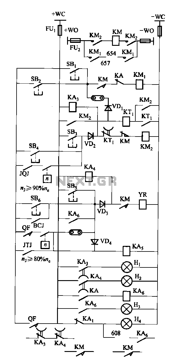
The FKL-32 type automatic thyristor excitation device is designed for synchronous generators with a terminal voltage of 400V and a capacity of 500kW and below. It is used for the automatic adjustment of excitation. The FKL-32 thyristor excitation device is...
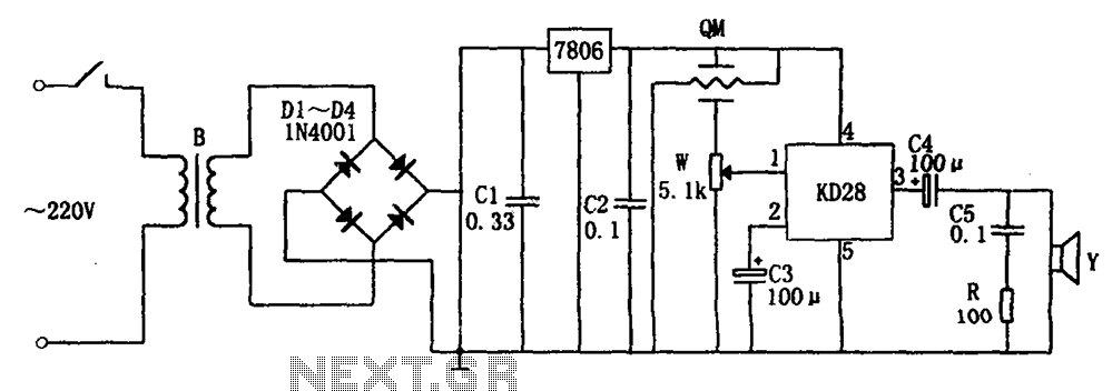
The system includes a gas-sensitive sensor element QM (type QM-N5), a buck rectifier, and regulator circuits, integrated circuits KD28, a speaker Y, and other components. The buck regulator circuit features a transformer rectifier and a bridge rectifier comprising diodes...
Active power factor correction stabilizes the electrical demand of a device to provide optimal power factor characteristics for various types of loads. To comply with power factor regulations, a cost-effective solution should be designed. In many applications, the requirement...
The circuit requires a double pole, double throw relay in conjunction with a single transistor to allow toggling the relay with a momentary push button. One set of relay contacts is used to control the load, while the other...
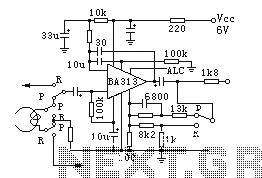
BA313 is a built-in automatic level control (ALC) circuit for audio recording preamplifiers, commonly used in cassette tape recorders. It is housed in a 9-pin dual in-line package (DIP) and features a wide range of automatic level control, operates...
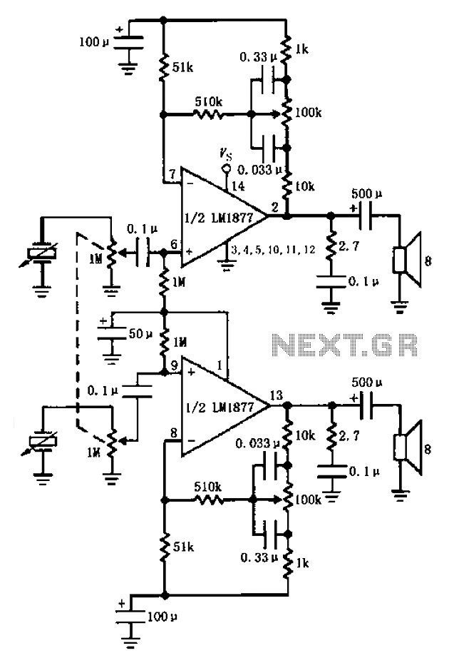
A bass player setup utilizing a stereo control is implemented through an LM1877 amplifier circuit. A cermet stereo microphone pickup is used to capture audio signals from a stereo turntable, with left and right channel outputs. The audio signals...