
House Alarm Loop

The alarm circuit is designed to provide a reliable security solution using a combination of open and closed loop switch contacts. The open loop contacts serve as sensors that detect unauthorized entry, while the closed loop contacts can be used for various applications, such as monitoring doors or windows. When any of the switches (1, 2, or 3) are triggered, the circuit activates the alarm system, ensuring immediate notification of a potential security breach.
The alarm remains active for a duration of 5 to 10 minutes, allowing sufficient time for an individual to respond to the alert. This time frame can be adjusted based on specific requirements or preferences. The inclusion of a 27-second triggering delay for both entrance and exit provides users with a grace period to deactivate the alarm before it becomes fully operational, thereby reducing false alarms during regular access.
To enhance user control, the circuit is equipped with a cancel button. This feature allows users to reset the alarm system back to its standby mode, ensuring that the system can be quickly reactivated without the need for a complete power cycle. The cancel button is strategically placed for easy access, promoting user-friendly operation.
Overall, this circuit design combines functionality with simplicity, making it suitable for various security applications where timely alerts and user control are paramount. Proper implementation of this circuit can significantly enhance security measures in residential or commercial settings.This circuit offers open and closed loop contacts (switches 1,2,3) that triggers the alarm ON and stays ON for 5 -10 minutes. The trigering delay (entrance/exit) is 27 seconds. This simple alarm circuit Has also a cancel button for reseting the circuit to stand-by mode again.. 🔗 External reference
Related Circuits

The high-temperature alarm will emit a beep and the LED will blink when the temperature of the device rises abnormally. This simple overheating alarm is designed to monitor heat levels. The high-temperature alarm circuit is an essential safety device used...
Before installing this or any other engine cut-off device in a vehicle, it is essential to carefully evaluate the safety implications of potential failures and the legal ramifications of implementing a device that could result in an accident. If...
When the switch is pressed, capacitor C3 charges through resistor R4 with a time constant of 0.47 seconds. Upon releasing the switch, C3 discharges more slowly through resistors R7 and R3, with a time constant of approximately 5 seconds....
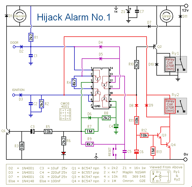
This is a simple single-zone burglar alarm circuit. Its features include automatic exit and entry delays. It is designed to be used with the usual types of normally-closed input devices such as magnetic reed contacts, micro switches, foil tape,...
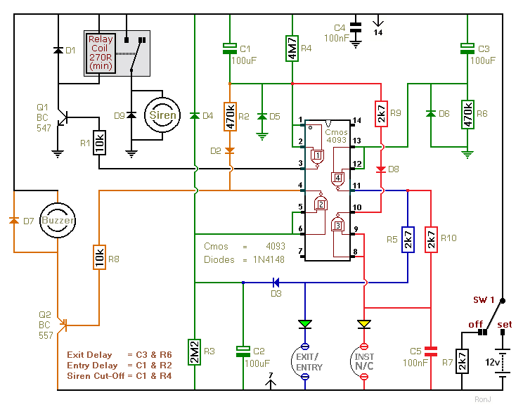
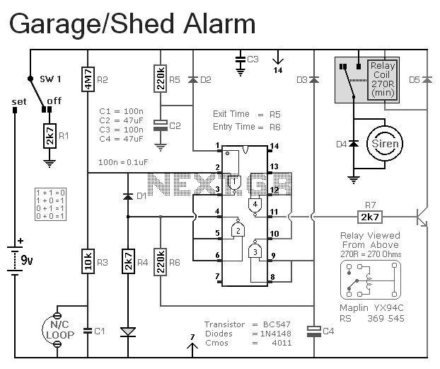
This two-zone alarm features automatic exit, entry, and siren cut-off timers. It was created for the Beginner's Guide to CMOS Timers, providing a particularly detailed circuit description. An optional One-Time-Only module is available, which forces the siren to switch...
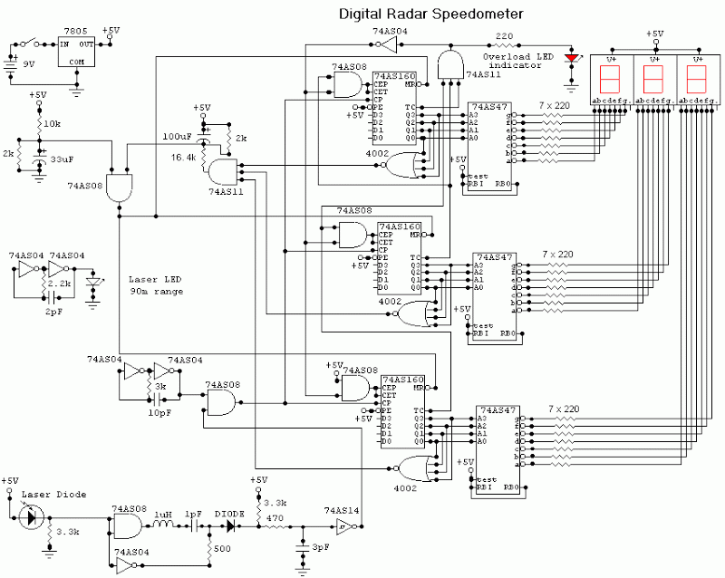
This digital alarm speedometer circuit allows for the measurement of the acceleration of any moving object, particularly cars and other vehicles. The acceleration is displayed in kilometers per hour (KPH) with a three-digit display. The system operates using laser...