
High Temperature Alarm Circuit

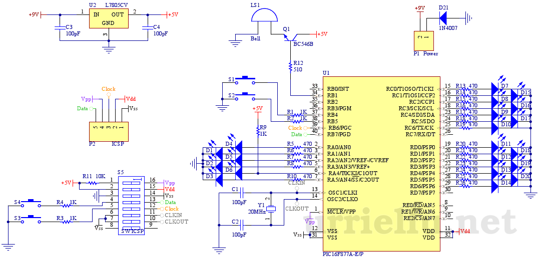
The high-temperature alarm circuit is an essential safety device used to detect abnormal temperature increases in electronic equipment or environments. The core components of this circuit typically include a temperature sensor, a microcontroller or comparator, an audible alarm (buzzer), and an LED indicator.
The temperature sensor, often a thermistor or an LM35 integrated circuit, continuously monitors the ambient temperature. When the temperature exceeds a predefined threshold, the sensor outputs a signal to the microcontroller or comparator. The microcontroller is programmed to interpret this signal and determine if the temperature is beyond acceptable limits.
Upon detecting an over-temperature condition, the microcontroller activates an audible alarm, usually a piezo buzzer, which emits a beeping sound to alert users of the potential overheating situation. Simultaneously, the microcontroller also triggers an LED to blink, providing a visual indication of the alarm condition. The blinking LED serves as an immediate visual cue that can be observed from a distance.
The circuit can be powered by a standard DC power source, and it may include additional features such as a reset button to silence the alarm and reset the system. Proper placement of the temperature sensor is critical to ensure accurate readings, and it should be positioned in a location that reflects the temperature of the device or environment being monitored.
In summary, this high-temperature alarm circuit is a straightforward yet effective solution for monitoring temperature and providing alerts to prevent overheating, thereby enhancing the safety and reliability of electronic devices.The high temperature alarm will beep and LED blinks when the temperature of the device increases abnormally. This simple over heat alarm is to monitor heat.. 🔗 External reference
Related Circuits

This circuit is designed to measure the inductance of an inductor labeled LX. The output of the circuit generates a TTL square wave, with its frequency being directly related to the inductance being measured. The output from the inductance...
This is the first electronic circuit designed from scratch, marking the initial experience with programming a microcontroller (MCU), the first application written in assembly language, and the second homemade printed circuit board (PCB). While it is common for individuals...

The objective is to enhance information transmission by utilizing articles. Please contact us via email at [email protected] within 15 days if there are issues related to article content, copyright, or other concerns. Prompt action will be taken to resolve...

The advantage of these compact Xbee modules is that they handle most of the complex tasks. The transmitter and receiver circuits are both straightforward. The primary components in the circuit include the Xbee Modules, PIC 18LF452, and LM317. Both...

This circuit utilizes a dedicated voice integrated circuit (AI) of the SK type, which incorporates an internal bistable multivibrator and three inverting amplifiers. The 555 integrated circuit (IC) A2 is employed for delay control. The described circuit is designed to...

This circuit employs a low-input-bias operational amplifier (op amp) to provide a stable DC indication of light levels. To decrease the sensitivity of the circuit to light, the resistor Rl can be reduced, although it should not be set...