
Shed/Garage Alarm

This burglar alarm circuit is designed for simplicity and effectiveness, providing an essential security feature for residential or small commercial applications. The circuit employs a standard configuration that includes a microcontroller or timer IC for managing the timing functions, alongside a relay to control the siren. The use of normally-closed input devices ensures that the circuit remains in a stable state until an intrusion is detected, at which point the circuit is disrupted, triggering the alarm.
The design is optimized for low power consumption, making it suitable for battery operation, which is critical in ensuring continuous monitoring without the need for frequent battery changes. The choice of input devices allows for flexibility in installation, accommodating various entry points such as doors and windows. The adjustable timing feature through R5 and R6 not only personalizes the alarm system but also enhances usability, allowing users to configure the system according to their daily routines.
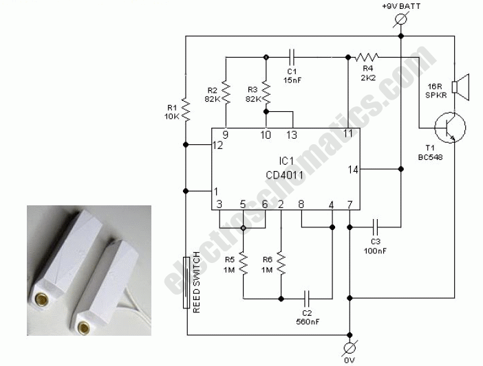
The inclusion of an LED indicator provides visual feedback, enhancing user experience by confirming the status of the alarm system. The circuit layout should be carefully designed to minimize noise and interference, ensuring reliable operation in diverse environments. Proper placement of components and routing of connections will also contribute to the overall performance and longevity of the burglar alarm system.This is a simple single-zone burglar alarm circuit. Its features include automatic Exit and Entry delays. It`s designed to be used with the usual types of normally-closed input devices such as - magnetic-reed contacts - micro switches - foil tape - and PIRs. It has an extremely small standby current - making it ideal for battery-powered operation. I`ve used a 9-volt battery in the diagram - but the circuit will work at anything from 5 to 15-volts. Just choose a relay and Siren suitable for the voltage you want to use. It`s easy to use. To set the alarm move SW1 to the "set" position. You now have about 10 to 15 seconds to leave the building. When you return and open the door - the green LED will light. You then have about 10 to 15 seconds to move SW1 to the "off" position. If you fail to do so - the relay will energize and the Siren will sound. Of course - you can turn the Siren off at any time by moving SW1 to the "off" position. Because of manufacturing tolerances - the precise length of any delay depends on the characteristics of the actual components you`ve used in your circuit.
But by altering the values of R5 & R6 you can adjust the Exit and Entry times to suit your requirements. Increasing the values increases the time - and vice-versa. 🔗 External reference
Related Circuits

This circuit is a laser alarm system similar to those depicted in various movies. It employs a laser pointer beam to secure valuables and property. When the beam is interrupted by a person, animal, or object, the resistance of...
The schematic represents a water level alarm circuit. This circuit functions as a water level sensor and emits a melodious alarm sound when the two probes within the circuit detect the presence of water. This water level indicator circuit...
Before installing this or any other engine cut-off device in a vehicle, it is essential to carefully evaluate the safety implications of potential failures and the legal ramifications of implementing a device that could result in an accident. If...
This PC Watcher circuit is designed to prevent unauthorized access to personal computers. After being constructed on a small piece of veroboard, it can effectively enhance security. The PC Watcher circuit operates by monitoring the status of the computer and...
This is a simple and easy-to-build multi-tone alarm circuit that can be utilized in burglar alarms or sirens. The circuit is based on the dual op-amp MC1458 and LM380. The two op-amps within the MC1458 are configured to generate...
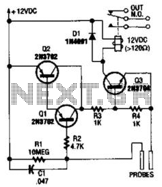
This circuit functions as a flood alarm using several bipolar transistors. When liquid comes into contact with the probes, a leakage current biases Q1, Q2, and Q3 (configured as a direct current-coupled amplifier) into conduction, thereby activating the relay....