
how to build a 2KVA inverter circuit diagram

The modified square wave inverter circuit operates by converting direct current (DC) into alternating current (AC) using a transformer. The circuit's core component is the transformer, which is responsible for stepping up the voltage to a suitable level for powering household appliances. The inverter's design allows for frequency adjustment through the variable resistor (VR 470k), which alters the timing of the switching elements in the circuit, thereby modifying the output frequency.
The inverter employs a solid transformer, which is more efficient compared to chopper-based designs. This type of transformer typically consists of a core made from magnetic material, with primary and secondary windings. The primary winding is connected to the DC power source, while the secondary winding delivers the AC output. The winding configuration and the number of turns in each winding are critical for determining the output voltage and current capacity of the inverter.
To ensure optimal performance, the transformer must be carefully wound according to specific guidelines. The wire gauge, number of turns, and core material all contribute to the efficiency and effectiveness of the inverter. A well-designed transformer will minimize losses, allowing the inverter to operate efficiently without excessive battery drain.
Additionally, the circuit may include protective components such as fuses or circuit breakers to prevent damage from overcurrent conditions. Capacitors may also be used to filter the output, smoothing out the waveform and reducing electromagnetic interference (EMI), which can be particularly important when powering sensitive electronic devices.
Overall, this modified square wave inverter circuit provides a cost-effective solution for converting DC to AC, making it suitable for various applications in residential settings. The ability to adjust the output frequency enhances its versatility, allowing it to power a range of appliances while maintaining energy efficiency.the diagram is a modify square wave inverter circuit diagram, and if you adjust the frequency by adjusting or turning the frequency resistor (VR 47Ok) the inverter output frequency can be strong enough to power a freezer compressor and some other electronics appliances in a living room. the circuit dont drain battery so fast and its very cheap to design. the inverter is not a chopper transformer circuit base inverter it is a solid transformer base inverter, i will take time to arrange how you can wind the transformer. 🔗 External reference
Related Circuits
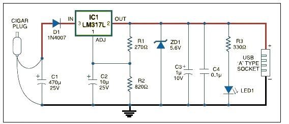
This USB car charger adapter project functions as a DC-DC power converter that effectively converts the 12V car battery voltage into a stable 5V output. It is designed to supply power from a car's cigar lighter socket to any...
The timing doorbell circuit utilizing the CW9300 is depicted in the provided diagram. This circuit features a timing function that, upon pressing the button, plays music for a specified duration. If the button is pressed again immediately after releasing...
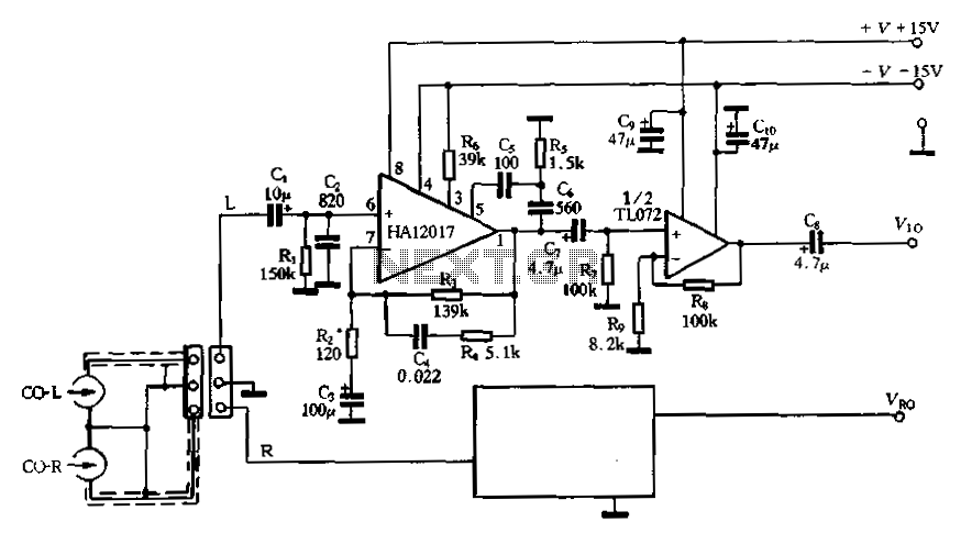
Figure 3-16 illustrates a low-noise preamplifier equalizing circuit using the HA12017. This circuit includes playback components R3, R4, and C4, which conform to a standard balanced network. The gain of the circuit is -7dB at 1kHz, while the output...
In this intercom schematic, an 8-ohm speaker is used as both a microphone and a listening speaker. A 10K potentiometer controls the volume, and the total gain can be adjusted. This intercom circuit utilizes an 8-ohm speaker in a dual...
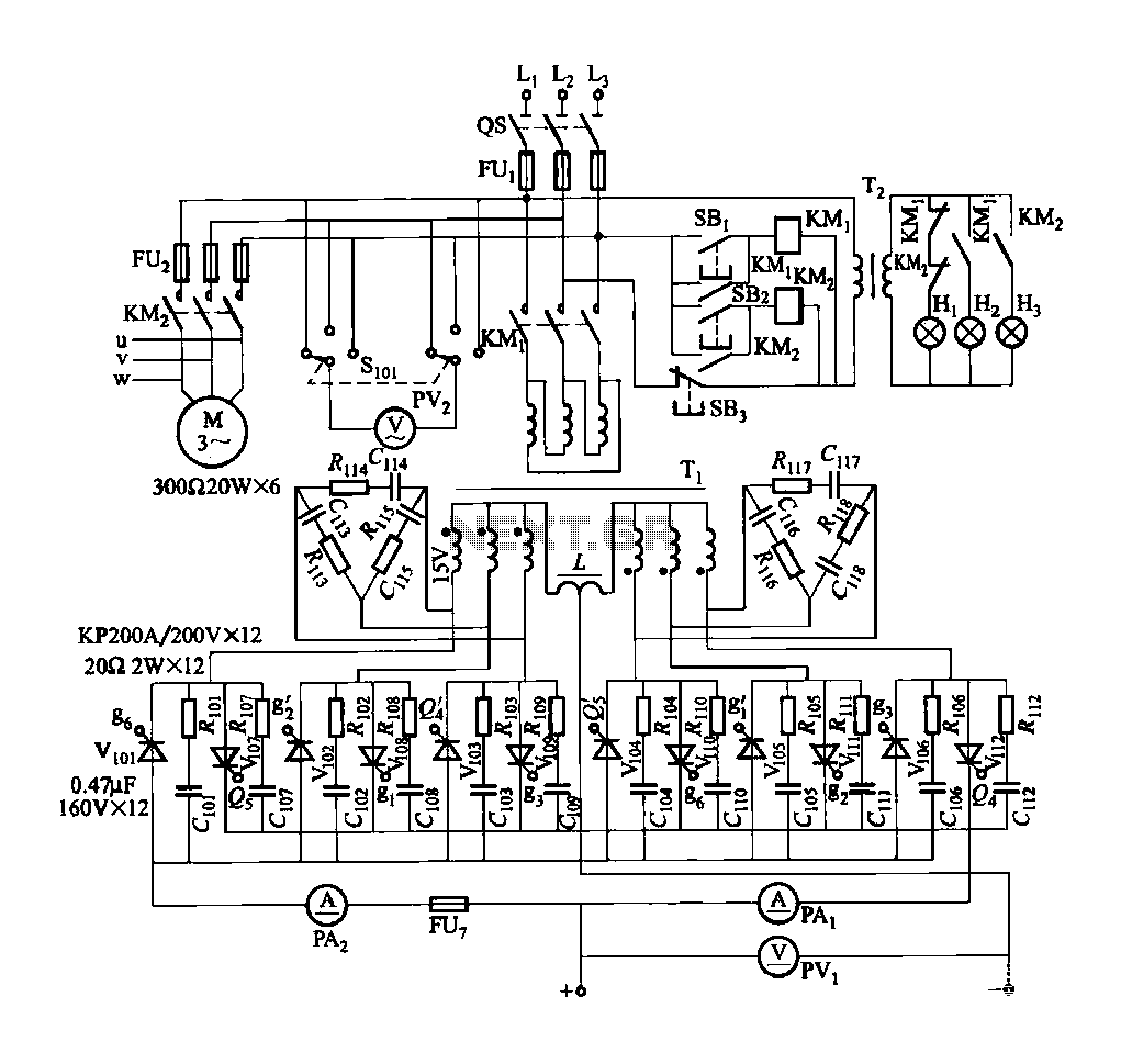
FGDF-3 is a three-phase low-temperature iron plating main circuit, while the KGDF-3 represents a low-temperature iron plating power supply device that includes characteristics of a single-phase low-temperature iron plating power supply. This device utilizes a three-phase power grid to...
XP power plug, FU fuse, ST temperature control, T1 low-voltage transformers, S1, S2 door interlock switch, S3 threshold control switch, RT thermal sensor, K1, K2 relay, EL furnace light, M1 wheel motor, M2 fan motor, T2 high-voltage transformer, C...