
Timing doorbell circuit diagram with CW9300

The timing doorbell circuit is designed to provide a user-friendly auditory notification system. The CW9300 integrated circuit serves as the core component, managing the timing and audio playback functions. When the button is pressed, the circuit initiates a timing sequence, allowing the user to hear a melody or sound for a predetermined number of seconds. This duration can typically be adjusted based on the specific requirements of the installation.
The circuit includes a push-button switch that serves as the input trigger for the system. Upon activation, the CW9300 generates a signal to drive a speaker or buzzer, producing the desired sound. The timing feature is crucial as it prevents the doorbell from ringing again if the button is pressed immediately after releasing it, thereby avoiding repetitive sounds that could be disruptive.
Additional components in the circuit may include resistors, capacitors, and possibly a diode, which help to manage the power supply and ensure stable operation. The power supply for the circuit can be derived from standard voltage sources, typically ranging from 5V to 12V, depending on the specifications of the CW9300 and the output device used.
Overall, the timing doorbell circuit with the CW9300 offers a reliable and efficient solution for doorbell applications, combining timing control with sound playback to enhance the user experience.Timing doorbell circuit with CW9300: As shown is Timing doorbell circuit diagram with CW9300. It has timing function, when we push the button,it will play musicforsome seconds, if we re-push the button immediately after loosing it, the doorbell will not ring either.. 🔗 External reference
Related Circuits
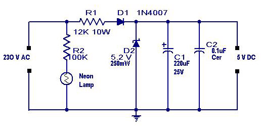
A simple transformerless power supply circuit with a diagram and schematics that provides a 5 volts DC output. This is a low-cost, low-current power supply circuit suitable for simple applications such as powering an LED. The transformerless power supply circuit...
This circuit is designed to detect whether the load of a battery charger or plug-in adapter is properly connected. The load may consist of a set of batteries needing charging or any other device that operates on low DC...
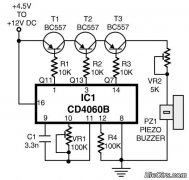
This is a simple home telephone ringtone generator circuit constructed using only a few electronic components. It generates a simulated telephone ringtone and requires a DC supply voltage ranging from 4.5V to 12V. This circuit can be used in...
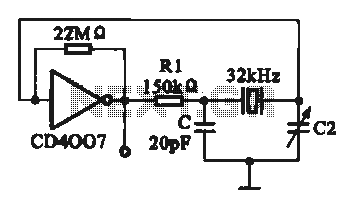
A 32 kHz clock oscillator is essential for digital circuits, as depicted in the schematic. The 32 kHz crystal clock oscillator serves to provide a time reference signal for the digital circuit. It utilizes a CMOS integrated circuit, specifically...
The TDA3567 is a monolithic integrated decoder designed for the NTSC color television standards. It incorporates all the necessary functions for the demodulation of NTSC signals. Additionally, it features a luminance amplifier and an RGB matrix amplifier. These amplifiers...
Figure 1 illustrates an AND gate logic circuit with the logic expression P=A. Figure B depicts two photodiodes connected in series. When the input logic levels A=1 and B=1, the output P=1. Similarly, this configuration can be used to...