
How to build a simple remote control system

The project involves the implementation of a radio frequency (RF) communication system utilizing Ming RF transmitter and receiver boards. The schematics have been updated to enhance clarity and detail, making it easier to identify the components and their connections. The RF transmitter operates by modulating a carrier frequency, which is then transmitted through a quarter-wave antenna. This type of antenna is chosen for its effectiveness in achieving a good balance between size and performance, providing an efficient radiation pattern.
The receiver is designed to demodulate the incoming RF signal, extracting the original information signal for further processing. The overall design emphasizes cost-effectiveness without compromising performance, making it suitable for hobbyists and educational purposes. The use of quarter-wave antennas contributes to extended operational range and improved signal quality, which is crucial for applications requiring reliable communication over distances.
Overall, the updated schematics reflect a comprehensive approach to RF design, incorporating best practices for component selection and circuit layout, ensuring that the system operates effectively in various conditions.Due to the huge interest in this project, I have just recently finished the NEW schematics. The older schematics were scanned and pretty poor quality. These new ones should make it considerably easier to recognize the parts used for the project. The Ming RF transmitter and receiver boards used for this project are relatively inexpensive and perform admirably considering the meager price. Using the quarter wave antennas, I have had some excellent results with operating distance as well as overall operation.
🔗 External reference
Related Circuits
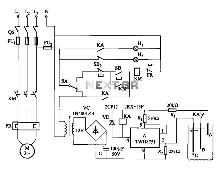
The power switch integrated circuit A features a straightforward design with high sensitivity, ensuring reliable operation. It is part of an automatic liquid level control circuit. When the water level at electrode B drops below 2 feet (0V), circuit...
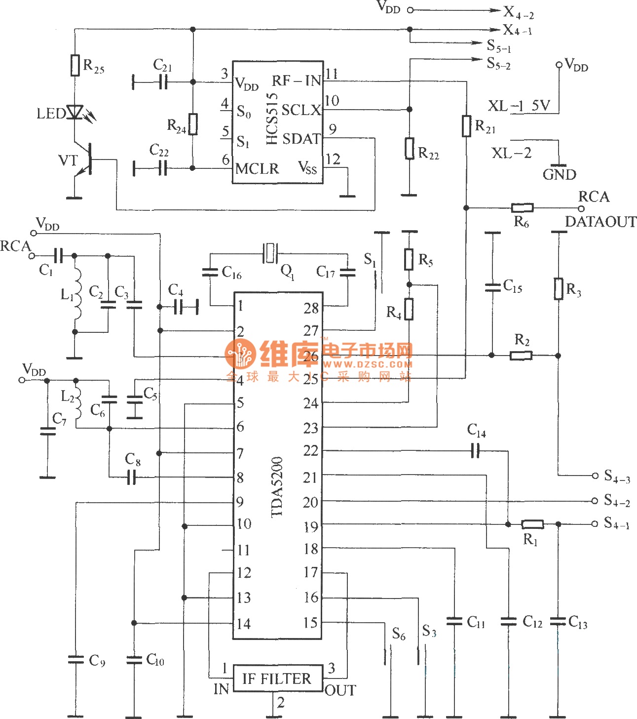
The TDA5200 is a low-power, single-chip ASK superheterodyne receiver circuit. It operates within two frequency blocks: 868 to 870 MHz and 433 to 435 MHz. This circuit is highly integrated, requiring minimal external components while offering excellent functionality. It...
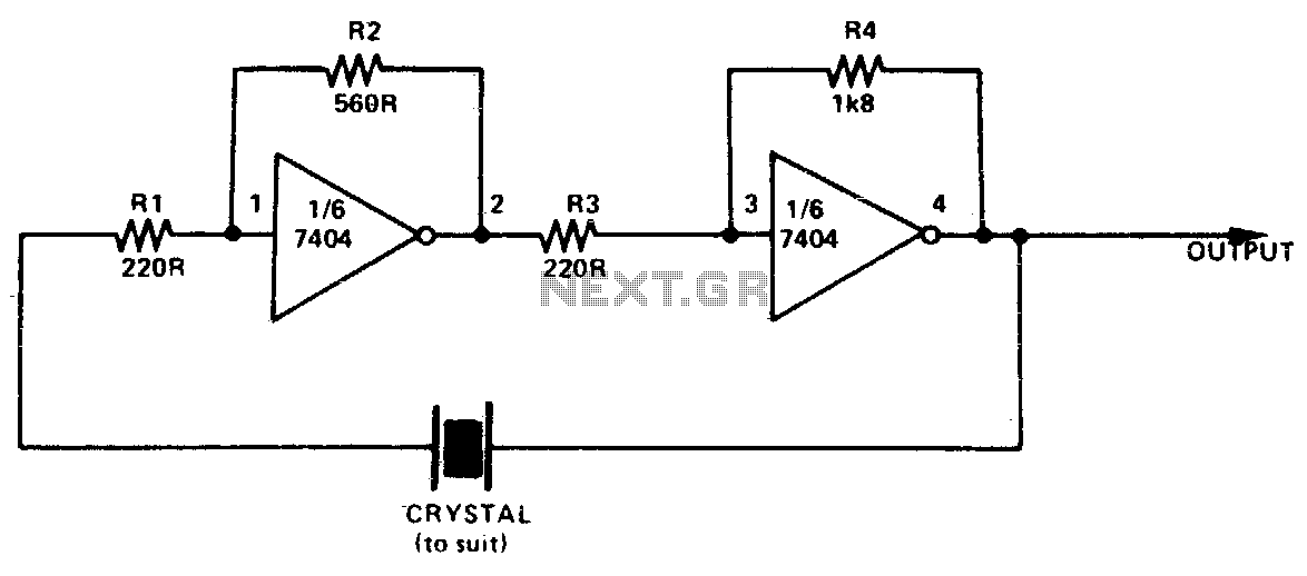
This simple and inexpensive crystal oscillator consists of one-third of a 7404 IC, four resistors, and a crystal. The inverters are biased into their linear regions by resistors R1 to R4, while the crystal provides the necessary feedback. Oscillation...
Questions frequently arise regarding the use of solar panels to power Fiber-To-The-Home (FTTH) equipment. This concept may seem unusual at first, but it is a practical solution for numerous businesses and municipalities. For instance, many municipalities have water towers,...
The hex switches are connected to J2 as follows: pin 1 is the common of both switches (+5V), pin 2 is the least significant bit (LSB) up to pin 5 which is the most significant bit (MSB) of the...
The power-supply controller features staggered voltage-output sequencing. Four voltage outputs are activated simultaneously for voltage tracking; two outputs are designated for core and I/O supplies during power-up, while the other two outputs cater to line driver supplies where tracking...