
L293 reversible motor drive circuit diagram

The described circuit employs TTL-compatible inputs and outputs, ensuring seamless integration with various digital logic systems. The totem pole configuration allows for efficient driving of loads, maximizing current delivery while maintaining low output impedance when active. The use of Darlington transistors enhances the current gain, enabling the circuit to control larger loads without excessive input current.
The enable signals (1,2 EN and 3,4 EN) play a critical role in managing the operation of the drivers. By applying a high signal to these inputs, the corresponding drivers are activated, allowing current to flow through the outputs. This feature is essential for applications requiring precise control over motor direction and operation, as it enables users to switch between forward and reverse motion by appropriately toggling the enable signals.
The L293 and L293D integrated circuits are specifically designed to handle inductive loads, which are common in motor control applications. The L293 can handle a continuous current of 1 A per channel, making it suitable for larger motors or multiple smaller motors. The L293D, with its lower current rating of 600 mA, is ideal for smaller applications or where space is a constraint. Both chips include built-in diodes for flyback protection, which safeguard the circuit from voltage spikes generated when inductive loads are switched off.
This configuration allows for the implementation of H-bridge circuits, which can control the direction of a motor by reversing the polarity of the voltage applied to its terminals. This capability is essential for applications such as robotics, where precise control over movement is required. The ability to place the outputs in a high impedance state when the drivers are disabled further enhances the versatility of the circuit, allowing for safe and efficient operation without risking damage to the components.
In summary, the combination of TTL compatibility, totem pole driver circuits, and the use of L293 and L293D integrated circuits provides a robust solution for controlling motors and solenoids in a variety of electronic applications. The detailed operation of the enable signals and the characteristics of the driver outputs ensure that this circuit can effectively manage the demands of high-current applications while maintaining reliability and efficiency.All input is compatible with TTL. Each output is a complete totem pole driver circuit, Darlington transistors chip and pseudo-Darling source. Driver enable, 1,2 EN and drivers 3 and 4 by a 3,4 EN Enable Enable drives 1 and 2. When the enable input is high, the associated driver is enabled, the output active in the input stage with them. When the enable input is low, these drivers are disabled, and the output is closed, in a high impedance state.
With the right data entry, each driver to form a complete H (or bridge) for reversible drive motor or solenoid applications. High current L293 quadruple half - driving integrated circuit H, we can design a very simple high-efficiency motor control L293 is designed to provide a voltage bidirectional drive current of 1 A 4.V to 3V is designed to provide the L293D bidirectional drive current 600 mA voltage from 4.V to 36 V.
both devices are designed to drive inductive loads, such as relays, solenoids, DC and bipolar stepper motors, and other high-current/high positive supply load voltage applications. All input is compatible with TTL. Each output is a complete totem pole driver circuit, Darlington transistors chip and pseudo-Darling source.
Driver enable, 1,2 EN and drivers 3 and 4 by a 3,4 EN Enable Enable drives 1 and 2. When the enable input is high, the associated driver is enabled, the output active in the input stage with them. When the enable input is low, these drivers are disabled, and the output is closed, in a high impedance state.
With the right data entry, each driver to form a complete H (or bridge) for reversible drive motor or solenoid applications.
Related Circuits
One of the critical components is a PWM speed controller, allowing for fine speed adjustments instead of just an "on" mode that runs at full power. This is important for safety. A basic stamp microcontroller was purchased, which includes...

A schematic of a typical transistor AM radio is presented. This circuit utilizes npn transistors. It is a generic circuit; hence, specific values for some components are not provided. This circuit serves as a reference point for experimenters. The schematic...
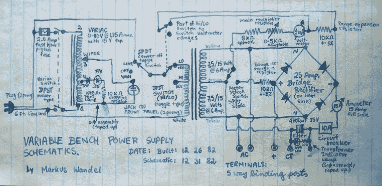
This power supply is able to deliver adjustable center-tapped DC from 0 to about 30 volts, as well as AC directly from the Variac and from the main transformer before the rectifier. What's primitive by today's standard is that...

To utilize this facility, the calling subscriber must first dial the standard phone number of the intended recipient. Once the call is connected, the calling party does not hear a ring-back tone. The calling subscriber must then press the...
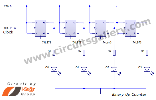
This document discusses an Asynchronous 4-Bit Binary Up Counter, a circuit constructed from several J-K flip-flops connected in a cascade configuration to produce a four-bit counting sequence. An up counter is a digital counting circuit that increments its count...
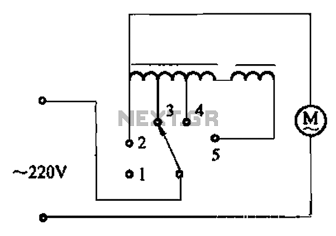
The circuit illustrated in Figure 3-2 features a loop reactor governor that incorporates a series reactor. The reactor can be constructed using a TV choke and is designed to be approximately 3mm in height. It utilizes a strength wire...