
2000W Power AmplifierCircuit Using The BC560C Transistor

The 2000W power amplifier circuit is designed to deliver high output power suitable for various applications, including audio amplification and RF transmission. The BC560C transistor, which is a PNP bipolar junction transistor, is utilized in this circuit for its ability to handle significant power levels while providing efficient amplification.
The circuit typically consists of a power supply section, input stage, driver stage, and output stage. The power supply must be capable of delivering sufficient voltage and current to support the 2000W output, often requiring a transformer and rectifier setup to convert AC to DC.
The input stage may include capacitors for coupling and DC blocking, ensuring that only the desired signal is amplified while preventing DC bias from affecting subsequent stages. The driver stage is responsible for providing adequate gain to drive the output stage, which consists of the BC560C transistors arranged in a push-pull configuration. This setup allows for efficient amplification of the input signal, with one transistor conducting during the positive half-cycle and the other during the negative half-cycle.
Feedback mechanisms may be employed to improve linearity and reduce distortion, ensuring high-fidelity output. Additionally, heat sinks are often necessary to dissipate the heat generated by the transistors during operation, maintaining optimal performance and preventing thermal overload.
Overall, this power amplifier circuit exemplifies a robust design capable of delivering substantial power output while maintaining signal integrity, making it suitable for demanding audio and RF applications. Proper attention to component selection and thermal management is essential for reliable operation.The following circuit shows about 2000W Power Amplifier Circuit Diagram. This circuit using the BC560C Transistor. Features: hard enough to .. 🔗 External reference
Related Circuits
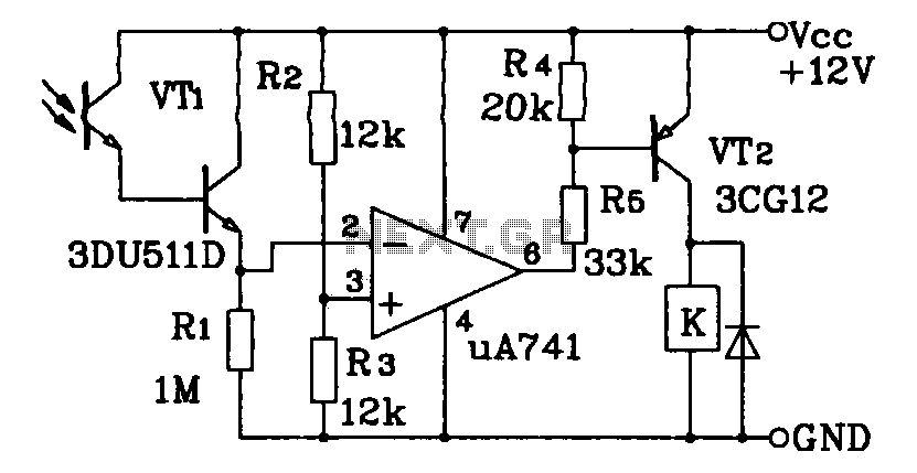
This circuit application utilizes a Darlington phototransistor for light-triggered switching. The design incorporates a Darlington phototransistor and an operational amplifier (op-amp), allowing the circuit to respond to very faint light levels. The circuit can be modified to trigger in...
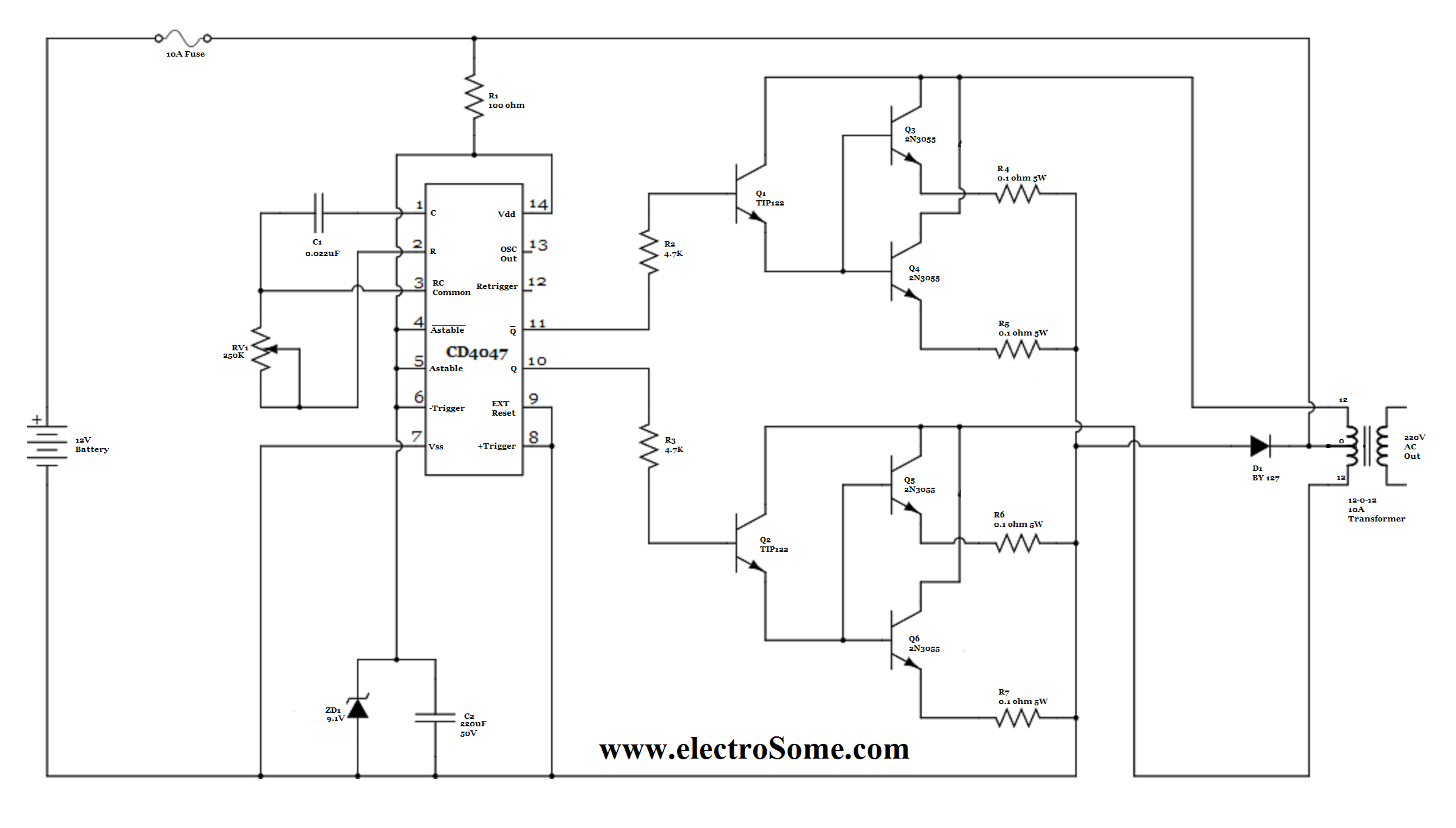
For basic requirements, square wave inverters can be utilized as they are simple, low-cost, and easy to construct. However, pure sine wave inverters are preferred for driving inductive loads. This document discusses a simple low-power square wave inverter using...
The following diagram represents a 20W power amplifier circuit constructed using the EL34 tube component. The EL34 is a well-known tube that is highly regarded for use in power tube amplifiers. The circuit includes both the tube amplifier schematic...
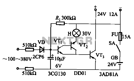
An AC-DC power supply without a power switching circuit is typically employed in lighting load circuits. When the power grid is restored, the standby power supply automatically switches on. The automatic switching circuit utilizes a transistor, as illustrated. The...
The circuit depicted in the figure is based on the RF2126, a 2450 MHz end-stage linear power amplifier. The radio frequency (RF) signal enters through input pin 1 and is subsequently amplified by the amplifier stages (pins 5, 6,...

Traditional soldering irons utilize mains AC supply for heating, which can be inconvenient in the absence of such a power source. This document describes a simple and cost-effective inverter circuit designed for use with standard soldering irons (25W, 30W,...