
how to make automatic vehicle headlight

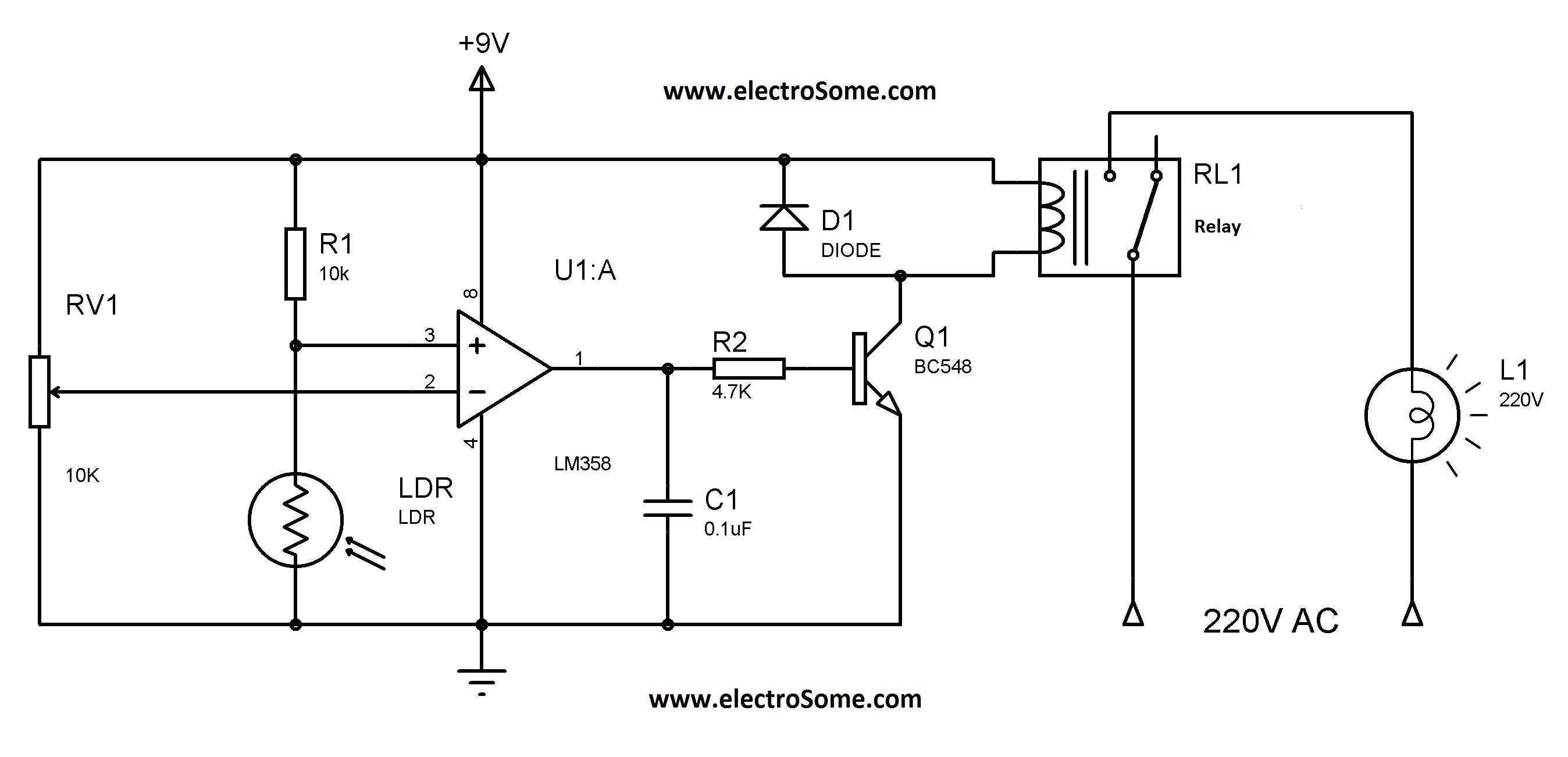
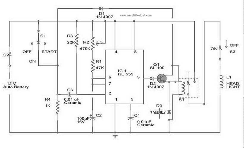
The automatic headlamp dipper circuit utilizes a light-dependent resistor (LDR) as a key component to detect incoming light. The LDR's resistance decreases when exposed to bright light, such as that from oncoming vehicle headlights. This change in resistance is crucial for the operation of the circuit. The transistor, functioning as a comparator, is connected to both the LDR and a preset resistor. When the LDR detects light, its resistance drops, which in turn increases the current flowing to the base of the transistor. The transistor, once activated, allows current to flow through its collector-emitter path, energizing the relay.
The relay serves as an electromechanical switch that controls the headlamp intensity. When the relay is activated, it changes the connection of the headlamps from the main filament to the dimmer filament, effectively "dipping" the headlights. This automatic adjustment helps prevent glare for oncoming drivers and enhances safety by allowing the driver to maintain focus on the road without the distraction of manual adjustments.
The circuit should be carefully designed to ensure that the LDR is positioned in a location that accurately represents the lighting conditions experienced by the driver. Proper enclosure of the circuit components is essential to protect against environmental factors, while ensuring that the LDR remains exposed to light sources. This design not only improves convenience for the driver but also contributes to safer driving practices during nighttime conditions. The implementation of such an automatic headlamp dimmer circuit can significantly enhance the driving experience by reducing the cognitive load on the driver, allowing for a more focused and safer journey.The circuitdescribed herecan be built and used in your vehicle for an automatic dipping and dimming operation of the headlamps, in response to the intense lights coming from an opposite vehicle headlamps. You must have come across this irritating situation while driving at night when you find the headlight focus from an opposite vehicle fallin
g straight in your eyes, making things difficult to assess, giving rise to a situation of a collision or some kind of possible accident. Such situations are normally tackled by using manual dipper switch mechanism, where the driver is prompted to "dip" the focus of his headlight, thus giving the opposite vehicle a chance to adjust his vehicle and also an indication that he too needs to "dip" his vehicle lamps.
However, doing the above operation manually, every now and then can become horribly laborious and troublesome, therefore if some kind of automatic system is Incorporated, can help to save this headache of the driver, especially while he is driving in stressful conditions and on dangerous highways. The following diagram describes a simple yet effective auto head lamp dipper or dimmer circuit. The transistor is used as a comparator, which compares the preset resistance level and the LDR resistance level with reference to ground.
Light falling over the LDR from the headlight of the vehicle coming from the front instantly lowers its resistance and allows more current to flow to the base of the transistor. The transistor conducts and activates the relay, which in turn flips the contacts such that the host vehicle`s headlamps gets connected with the dipper filament, changing its intensity.
The whole circuit may be enclosed in a small box and installed somewhere near the driver`s dashboard area, however the LDR needs to be wired and placed out of the enclosure, in some corner of the wind shield, so that it is able to "see` the light from the opposite vehicles just as the driver would see them. 🔗 External reference
Related Circuits
Similar to the previous circuit utilizing the LM358, this design is also cost-effective, priced under 100 rupees. It is a circuit intended for the automatic control of street lights and garden lights. Users do not need to manually turn...
An automatic light system is integrated with a telephone block system. When the phone rings, the owner is prompted to pick up the handset or pull a lever, causing the lamp to light up. If there is no contact...
R2 must be adjusted to establish the correct finish charge voltage. Flooded and gel batteries are typically charged to 13.8V. For cycling batteries, such as AGM or gel types, battery manufacturers generally recommend a voltage range of 14.5V to...
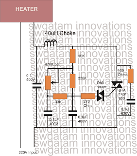
Controlling heaters rated up to 1500 watts requires stringent specifications for the controlling unit to ensure safe and effective operation. The introduction of advanced snubber-less Triacs and Diacs has made it relatively easier to implement heater controllers at high...
Automatic door control systems typically have a high market price for finished products. The proposed method is suitable for home use, utilizing easily accessible components. This design is ideal for those interested in creating their own automatic door system....
The circuit diagram for the automatic headlights turn-off circuit is presented here. This circuit can be installed in a car. The automatic headlights turn-off circuit is designed to enhance vehicle safety and convenience by ensuring that the headlights are automatically...