
HOW TO READ CIRCUIT DIAGRAMS

The process of reading circuit diagrams involves understanding the symbols and connections that represent electronic components and their interrelations. Key components include resistors, capacitors, diodes, transistors, and integrated circuits, each represented by standardized symbols. Familiarity with these symbols is essential for accurately interpreting the function and layout of a circuit.
Once the circuit diagram is understood, the next step involves assembling the circuit on a breadboard. A breadboard is a reusable platform that allows for the easy construction of electronic circuits without soldering. It consists of a grid of holes that facilitate the insertion of components and jumper wires, enabling quick modifications and troubleshooting.
To begin assembling a circuit on a breadboard, the first step is to identify the power supply requirements, ensuring that the correct voltage and current ratings are adhered to. Next, components should be placed on the breadboard according to the schematic, ensuring that the connections align with the intended design. It is crucial to maintain proper polarity, especially for polarized components such as electrolytic capacitors and diodes.
After placing the components, jumper wires can be used to connect them according to the circuit diagram. It is advisable to follow a systematic approach, connecting one section of the circuit at a time to minimize errors. Once the assembly is complete, the circuit can be powered on for testing.
Throughout the process, verification of connections is essential to ensure functionality. If the circuit does not operate as expected, troubleshooting steps should be undertaken, such as checking for loose connections or incorrect component placements. This hands-on experience is invaluable for understanding electronic principles and developing practical skills in circuit design and assembly.this instructable will show you exactly how to read all those confusing circuit diagrams and then how to assemble the circuits on a breadboard!for all.. 🔗 External reference
Related Circuits
The circuit diagram illustrates a voltage regulator designed from discrete components to meet specific voltage requirements. It provides two sets of component values for output voltages of 6.3 V (upper) and 12.6 V (lower). The components used include BC547...
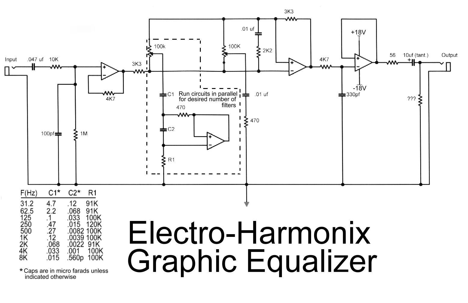
This is the diagram of the Electro-Harmonix graphic equalizer. The number of channels can be specified according to requirements by paralleling the components: C1, C2, R1, an operational amplifier, potentiometer, and a 470-ohm resistor. The frequency to be boosted...
This sound-controlled lighting circuit design is utilized to adjust the brightness of connected lights in synchronization with captured sound. The sound-controlled lighting circuit operates by detecting audio signals through a microphone or sound sensor. The circuit typically consists of several...
The circuit described here is that of a metal detector. The operation of the circuit is based on the superheterodyning principle, which is commonly used in superhet receivers. The circuit utilizes two RF oscillators. The frequencies of both oscillators...
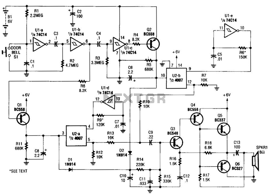
When the doorbell switch is pressed, two monostable stages are sequentially activated, applying bias to a pair of voltage-controlled resistor stages. These stages modulate the outputs from a pair of tone generators. The resulting signals are then fed to...
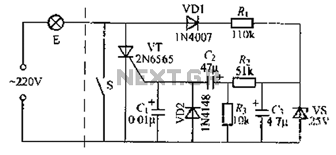
A delay circuit using an improved quenching lamp pull switch is described, focusing on its performance and the delay function in lighting control. The circuit exhibits a high degree of stability and reliability. When switch S is closed, the...