
How to Troubleshoot a Gas Dryer with No Heat

To troubleshoot the ignition system further, it is essential to understand the roles of the centrifugal switch and pressure switch in the operation of the burner assembly. The centrifugal switch, typically found in blower motors, is responsible for engaging or disengaging components based on the speed of the motor. When the motor reaches a specific RPM, the centrifugal switch closes, allowing power to flow to the ignition system. To test the centrifugal switch, it is necessary to ensure that the motor is functioning correctly and reaching its operational speed. A multimeter can be used to check continuity across the switch contacts when the motor is running. If there is no continuity, the switch may be faulty and require replacement.
The pressure switch, on the other hand, monitors the pressure levels within the combustion chamber or venting system. It is designed to ensure that the system is safe to operate by confirming that there is adequate airflow or pressure before allowing the ignition sequence to proceed. To test the pressure switch, a manometer can be used to measure the pressure at the switch’s input port while the system is operating. If the pressure is within the specified range but the switch does not close, it may be defective. Additionally, verifying the wiring and connections to the pressure switch is crucial, as loose or corroded connections can lead to operational failures.
In summary, a systematic approach involving the testing of both the centrifugal switch and pressure switch using appropriate tools will aid in diagnosing the root cause of the ignition failure. Ensuring that all safety switches and components are functioning correctly is vital for the safe operation of the system.No fire replaced ignitor still no fire checked for voltage to valve assy none checked safety switches on fire box & vent normally closed condition okayhow do I check the centrifical switch & pressure switch for proper operation.. 🔗 External reference
Related Circuits
This heatsink temperature monitor circuit uses three LEDs to signal when the temperature exceeds two boundary levels. When the heatsink temperature is below 50-60°C (122-140°F), the green LED lights up. The yellow LED indicates that the temperature is between...
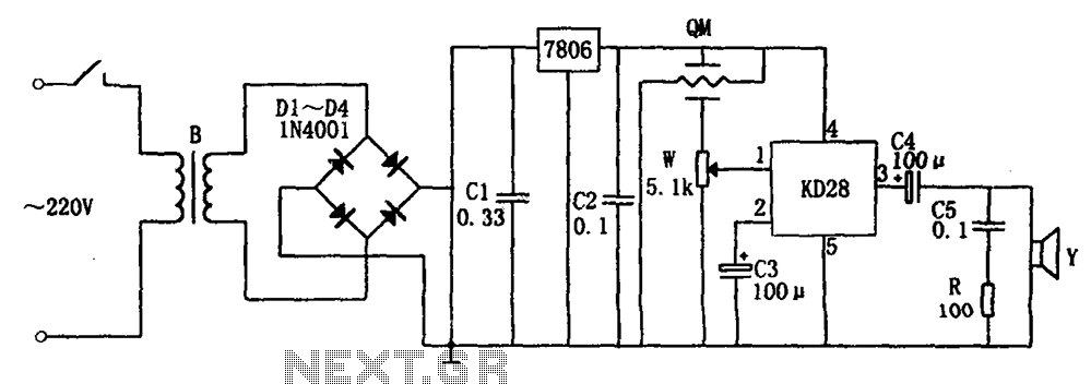
The system includes a gas-sensitive sensor element QM (type QM-N5), a buck rectifier, and regulator circuits, integrated circuits KD28, a speaker Y, and other components. The buck regulator circuit features a transformer rectifier and a bridge rectifier comprising diodes...

This regulator achieves 90% efficiency with a 12-V input and a 5-V output. It utilizes the LT1158 and LT1431 components from Linear Technology, Inc. High efficiency is accomplished by synchronously switching two power MOSFETs in a step-down switching regulator....
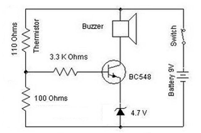
A heat sensor circuit can be utilized to control any device using a heat sensor. In this circuit, a thermistor and a resistor are connected in series, forming a potential divider circuit. The thermistor is of the Negative Temperature...
Writing about multiple circuits in Marx, an entire new set has been discovered, referred to as "the" Marx Generator. There are diagrams available, along with a useful quote: "The main advantage of the Marx circuit configuration over a more...

The initial step involves searching online for information. After some investigation, it was discovered that the QAA75 sensor is manufactured by Siemens. This expanded the search parameters. It was found that Siemens refers to the communication method as a...