
How to work with External Interrupts in AVR micro controller (Atmega8)
")
The Atmega8 microcontroller is a versatile device widely used in embedded systems, particularly for applications requiring external interrupt handling. External interrupts allow the microcontroller to respond immediately to external events, enhancing its ability to interact with the environment.
In this demonstration, the circuit is designed to showcase how an external interrupt can be triggered by a push-button switch. The circuit typically includes the Atmega8 microcontroller, a resistor, a capacitor, and the push-button switch connected to one of the external interrupt pins, such as INT0.
When the button is pressed, the voltage at the interrupt pin changes, signaling the microcontroller to execute the ISR. The ISR is a special function written in C that defines the actions to be taken when the interrupt occurs. For example, the ISR could toggle an LED, increment a counter, or send a signal to another part of the system.
The circuit diagram would illustrate the connections between the Atmega8 and the components, ensuring that the pull-up resistor is properly connected to maintain a stable high state until the button is pressed. The microcontroller's configuration registers must be set to enable the external interrupt and define its triggering condition (rising edge, falling edge, or both).
The C code would typically include the necessary header files, initialization of the microcontroller, configuration of the interrupt registers, and the ISR definition. The code should also contain a main loop that allows the microcontroller to remain in a low-power state or perform other tasks while waiting for the interrupt to occur.
This demonstration effectively illustrates the functionality of external interrupts in the Atmega8 microcontroller, providing a practical application for those learning about embedded systems and real-time processing.A demo of external interrupts in AVR (Atmega8) micro controller with circuit diagram and C code/program as ISR (interrupt service routine).. 🔗 External reference
Related Circuits
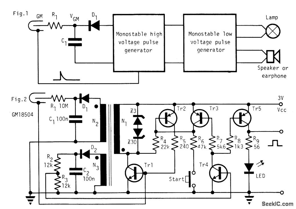
In the absence of radiation, no current is drawn. At normal background radiation levels, the power consumption is extremely low. The instrument may be left on for several months without changing batteries. In this way, the detector is always...
This circuit is primarily designed to provide a microphone input for standard home stereo amplifiers. Utilizing a battery supply effectively eliminates the risk of low-frequency hum interference from mains power, simplifying the connection to the amplifier by removing the...
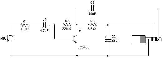
Most sound card microphone inputs require a minimum signal level of at least 10 millivolts, but some older 8-bit cards need as much as 100 millivolts. The typical impedance of the PC sound card microphone input is in the...
A microphone amplifier designed for use with either Electret Condenser Microphone (ECM) inserts or dynamic inserts, constructed with discrete components. The preamplifier circuit is self-stabilizing and sets its quiescent point at approximately half the supply voltage at the emitter...
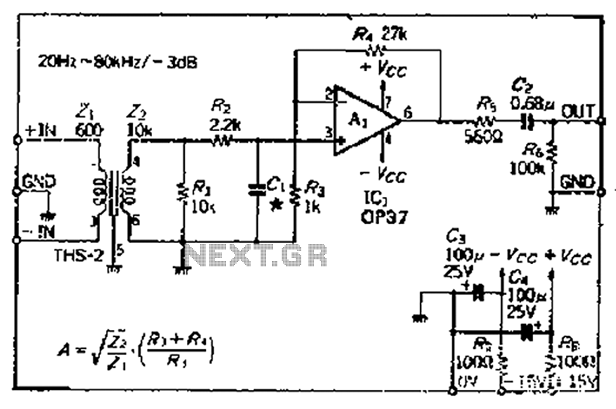
The common mode signal rejection ratio is influenced by the input transformer, which should either be a commercially available or a well-balanced homemade transformer. It is important to note that as frequency increases, the balance may decrease. The transmission...
This 555 timer based PWM controller features almost 0..100% pulse width regulation using R1, while keeping the oscillator frequency relatively stable. The frequency is dependent on values of R1 and C1, values shown will give a frequency range from...